
The Ultimate Guide to CNC Inserts: Types, Materials, and Applications
Introduction:
CNC inserts are replaceable cutting elements used in CNC turning, milling, drilling, threading, grooving and parting tools. In professional cutting-tool catalogs, most of these products are classified as indexable inserts because a worn cutting edge can often be rotated or replaced without replacing the complete toolholder or cutter body.
Common CNC insert names include CNMG, WNMG, TNMG, DNMG, VNMG, CCMT, DCMT, APKT, APMT, RPMT, LNMU, SPMT and threading insert families such as 16ER and 16IR.
However, the insert name alone is not enough to select the correct tool. You also need to consider:
- Machining operation;
- Insert shape and size;
- Workpiece material;
- Cutting geometry or chipbreaker;
- Carbide grade and coating;
- Corner radius;holder or cutter compatibility;
- Cutting speed, feed and depth of cut.
This guide explains the most common CNC insert types, names, materials, codes and applications, and shows how to select the correct insert for a machining operation.
CNC Inserts at a Glance
| Question | Quick Answer |
|---|---|
| What is a CNC insert? | A replaceable cutting element mounted in a CNC toolholder or cutter body |
| What are the main CNC insert types? | Turning, milling, drilling, threading, grooving and parting inserts |
| What are common CNC insert names? | CNMG, WNMG, TNMG, CCMT, DCMT, APKT, APMT, RPMT, SPMT and others |
| What are CNC inserts made from? | Carbide is the most common; cermet, ceramic, CBN and PCD are also used |
| Are CNC insert codes universal? | Basic ISO designation features may be standardized, but grade and chipbreaker codes are manufacturer-specific |
| Can two inserts with the same basic code perform differently? | Yes. They may use different geometries, carbide grades, coatings and edge preparations |
| Are CNC inserts universal between holders? | No. The complete dimensions and toolholder or cutter compatibility must be confirmed |
What Is a CNC Insert?
A CNC insert is a replaceable cutting element used in a CNC cutting-tool system.
The insert is mounted in a reusable:
- Turning toolholder;
- Boring bar;
- Milling cutter;
- Indexable drill;
- Grooving holder;
- Threading holder.
When a cutting edge becomes worn, the operator can normally rotate the insert to another usable edge or replace the insert while keeping the tool body.
This is why CNC inserts are commonly described as indexable inserts.
However, “CNC insert” is mainly a practical search and purchasing term. Professional tooling systems are more commonly organized by machining operation, such as:
- Turning inserts;
- Milling inserts;
- Drilling inserts;
- Threading inserts;
- Grooving and parting inserts.
CNC Insert vs Indexable Insert
The two terms often overlap, but they emphasize different things.
CNC insert describes a replaceable cutting insert used on CNC equipment.
Indexable insert describes the tooling concept: the insert provides replaceable or indexable cutting edges mounted in a reusable holder or cutter.
Therefore, most carbide inserts used in CNC turning and milling are also indexable inserts.
Nomenclature
How to Read a CNC Insert Code
CNC insert designations normally contain standardized geometric information followed by manufacturer-specific geometry and grade identifiers.
Consider the common turning insert:
CNMG 120408
C — Insert Shape
C identifies an 80° diamond or rhombic insert.
N — Clearance Angle
N indicates a 0° basic clearance angle.
M — Tolerance Class
M identifies the dimensional tolerance class.
It does not identify:
- Medium machining;
- Workpiece material;
- Carbide grade;
- Coating.
G — Insert Type
The fourth letter describes additional standardized characteristics of the insert construction and clamping configuration.
It should not be interpreted as a universal chipbreaker code.
12 — Insert Size
For a typical CNMG120408 insert, this corresponds to an approximately 12.7 mm inscribed circle.
04 — Thickness Code
For this example, nominal thickness is approximately 4.76 mm.
08 — Corner Radius
08 represents a nominal 0.8 mm corner or nose radius.
What Does the CNC Insert Code Not Tell You?
The base code CNMG120408 does not fully identify:
- Chipbreaker geometry;
- Carbide grade;
- Substrate;
- Coating;
- Edge preparation;
- Finishing or roughing application;
- Recommended feed;
- Recommended depth of cut;
- Recommended cutting speed.
For purchasing purposes, always provide the complete manufacturer code.
For example:
CNMG120408 + chipbreaker + grade
is much more useful than simply:
CNMG120408ation.
CNC Insert Shapes and Their Uses
Different insert shapes provide different combinations of cutting-edge strength and profiling accessibility.
| Shape | Typical Letter | Relative Strength | Accessibility | Typical Application |
| Round | R | Very high | Limited | Heavy cuts, profiling |
| Square | S | High | Moderate | Roughing, milling |
| 80° Diamond | C | High | Good | General turning |
| 80° Trigon | W | Medium-high | Good | General turning |
| Triangle | T | Medium | Good | General machining |
| 55° Diamond | D | Medium | Very good | Profiling |
| 35° Diamond | V | Lower | Excellent | Fine profiling |
A larger included angle generally provides a stronger cutting corner.
A smaller included angle gives the tool better access to complex profiles but leaves less material supporting the nose.
Therefore, the strongest insert shape is not always the best insert shape.
Types of CNC Inserts
Turning and Boring Inserts
Turning inserts are used on CNC lathes and turning centers for operations including:
- External turning;
- Facing;
- Profiling;
- Chamfering;
- Boring;
- Internal turning.
Common insert families include:
The choice depends largely on:
- Insert shape;
- Edge strength;
- Profiling access;
- Positive or negative clearance;
- Cutting force;
- Workpiece material.
Boring should not normally be treated as a completely separate insert family. Many boring bars use the same positive turning inserts, such as CCMT and DCMT, that are also used for external turning.
Milling Inserts
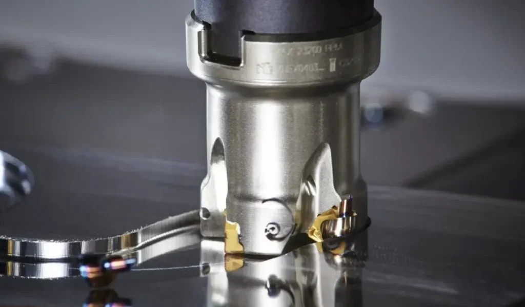
Milling inserts are mounted in rotating cutter bodies.
Typical applications include:
- Face milling;
- Shoulder milling;
- Slot milling;
- Side milling;
- High-feed milling;
- Profile milling;
- Pocketing.
Common milling insert families include:
- APKT;
- APMT;
- RPMT;
- RDMT;
- LNMU;
- SEKT;
- Other cutter-specific geometries.
Milling inserts should be selected according to:
- Cutter body;
- Entering angle;
- Feed per tooth;
- Axial depth of cut;
- Radial width of cut;
- Workpiece material;
- Machine stability.
Drilling Inserts
Indexable drilling systems use replaceable cutting inserts mounted in a drill body.
Depending on the tool design, the inner and outer inserts may experience significantly different cutting speeds and loads.
Common insert styles include SPMT, WCMX and other manufacturer-specific drilling geometries.
Indexable drilling is particularly useful when:
- Larger hole diameters are required;
- High material-removal rates are needed;
- Insert replacement is more economical than replacing the complete tool.
Do not confuse an indexable drill with an exchangeable-head drill. An exchangeable-head system replaces the complete cutting head rather than indexing individual inserts.
Threading Inserts
Threading inserts produce a controlled thread profile.
Common designations include:
- 11ER / 11IR;
- 16ER / 16IR;
- 22ER / 22IR.
ER usually identifies an external threading application within a manufacturer’s system, while IR is commonly used for internal threading.
Threading inserts may also be classified as:
- Full-profile;
- Partial-profile;
- Multi-tooth;
- Standard-specific geometries.
Selection must match:
- Thread standard;
- Pitch;
- Internal or external thread;
- Holder;
- Cutting direction;
- Workpiece material.
Grooving and Parting Inserts
Grooving and parting inserts are designed for narrow cutting operations.
Typical applications include:
- External grooving;
- Internal grooving;
- Face grooving;
- Profiling;
- Parting-off.
Important selection factors include:
- Groove width;
- Depth;
- Insert overhang;
- Holder rigidity;
- Workpiece diameter;
- Chip evacuation.
CNC Insert Name List and Uses
CNC inserts are usually identified by a combination of letters and numbers. Some insert families are designed primarily for turning, while others are intended for milling, drilling, threading or grooving.
The following table lists common CNC insert names and their typical applications.
| CNC Insert Name | Main Type | Basic Shape / Style | Typical Uses |
| CNMG | Turning | 80° negative diamond | General turning, medium machining and roughing |
| WNMG | Turning | 80° trigon | General turning with economical multi-edge use |
| TNMG | Turning | 60° triangle | General turning and facing |
| DNMG | Turning | 55° negative diamond | Profiling and general turning |
| VNMG | Turning | 35° negative diamond | Fine profiling and complex contours |
| SNMG | Turning | Square negative | Heavy and general turning |
| CCMT | Turning / Boring | 80° positive diamond | Internal turning, boring and light external turning |
| DCMT | Turning / Boring | 55° positive diamond | Profiling, boring and finishing |
| SCMT | Turning / Boring | Square positive | General internal and external turning |
| VBMT | Turning | 35° positive diamond | Fine profiling and finishing |
| APKT | Milling | Positive parallelogram | Shoulder milling, end milling and general milling |
| APMT | Milling | Positive parallelogram | Shoulder milling and general-purpose milling |
| RPMT | Milling | Round | Profile milling and general milling |
| RDMT | Milling | Round | Profiling and cutter-specific milling applications |
| LNMU | Milling | High-feed style | High-feed milling and high-productivity roughing |
| SEKT / SEHT | Milling | Square | Shoulder and face milling |
| SPMT | Drilling / Milling | Square positive | Indexable drilling and tool-specific milling |
| WCMX | Drilling | Trigon-style | Indexable drilling |
| 16ER | Threading | External threading profile | External CNC threading |
| 16IR | Threading | Internal threading profile | Internal CNC threading |
| MGMN | Grooving / Parting | Grooving style | Grooving and parting operations |
Important: This table describes common insert families, not universal applications. The exact use depends on the complete insert designation, geometry, grade and compatible holder or cutter.
CNC Insert Materials
The cutting material determines how the insert handles:
- Heat;
- Abrasive wear;
- Fracture;
- Chemical interaction with the workpiece;
- Cutting speed.
Carbide Inserts
Cemented carbide is the most widely used material for general CNC machining.
Advantages include a useful balance of:
- Hardness;
- Toughness;
- Wear resistance;
- Heat resistance;
- Cost.
Modern carbide inserts can be supplied with:
- PVD coatings;
- CVD coatings;
- Uncoated polished surfaces;
- Application-specific edge treatments.
Carbide is available for steel, stainless steel, cast iron, aluminum, titanium and many other workpiece groups, but the correct grade must still be selected.
Cermet Inserts
Cermet is often selected for:
- Steel finishing;
- Semi-finishing;
- Applications requiring stable surface finish.
Advantages may include:
- Good wear resistance;
- Chemical stability;
- Reduced tendency to weld to some steel workpieces.
The main limitation is generally lower toughness compared with many carbide grades.
Ceramic Inserts
Ceramic cutting materials provide excellent hot hardness and wear resistance.
They are commonly associated with:
- Cast iron;
- Hardened materials;
- Selected heat-resistant alloy applications.
However, ceramic inserts are relatively brittle and usually require:
- Stable machines;
- Rigid workholding;
- Suitable cutting parameters.
CBN Inserts
CBN and PCBN inserts are primarily used for hardened ferrous materials.
Typical applications include:
- Hard turning;
- Hardened bearing steels;
- Hardened gears;
- Hardened tool steels.
CBN grades may be designed differently for:
heavy interruption.
continuous cutting;
light interruption;
PCD Inserts
PCD is used mainly for non-ferrous and abrasive materials such as:
- Aluminum alloys;
- High-silicon aluminum;
- Copper alloys;
- Composites.
PCD is not normally used for conventional machining of ferrous steels.
CNC Insert Grade vs Geometry vs Coating
These terms are related, but they do not mean the same thing.
| Feature | Main Function |
| Insert shape | Determines corner strength and machining access |
| Geometry / chipbreaker | Controls chip formation, cutting forces and edge strength |
| Edge preparation | Controls sharpness and microchipping resistance |
| Grade | Balances wear resistance, toughness and heat resistance |
| Coating | Protects against friction, heat and wear |
| Corner radius | Influences edge strength, finish and cutting forces |
Geometry
The insert geometry includes features such as:
- Rake angle;
- Chipbreaker;
- Land;
- Edge hone;
- Cutting-edge preparation.
A finishing geometry may be sharp and positive.
A roughing geometry is usually more strongly supported.
Grade
The grade describes the cutting-material system.
For carbide inserts this may include:
- Carbide substrate;
- Grain structure;
- Binder;
- Coating;
- Post-treatment.
A more wear-resistant grade is not automatically better.
An interrupted cut may require additional toughness.
Coating
Common carbide coating systems include:
- PVD;
- CVD;
- Multilayer coatings;
- Specialized low-friction coatings.
Do not select an insert from coating color alone.
What Are Different CNC Inserts Used For?

The most useful way to understand CNC insert applications is to match the insert family to the machining operation, rather than only listing end-use industries.
CNMG / WNMG
Commonly used for:
- General turning;
- Facing;
- Medium machining;
- Roughing.
DNMG / VNMG
Commonly selected where:
- Profiling access is important;
- Complex contours must be machined;
- Smaller included angles are required.
CCMT / DCMT
Common applications include:
- Boring;
- Internal turning;
- Light external turning;
- Finishing;
- Lower-force machining.
APKT / APMT
Commonly used in:
- Shoulder milling;
- End milling;
- Side milling;
- General indexable milling.
For a detailed comparison between these two families, read:
APMT vs APKT Inserts: Differences and Compatibility
RPMT / Round Milling Inserts
Common applications include:
- Profile milling;
- Contour milling;
- Roughing;
- Applications requiring a strong cutting edge.
LNMU and High-Feed Inserts
Used primarily for:
- High-feed milling;
- Shallow axial cuts;
- High metal-removal rates;
- Long-overhang applications where directing forces axially can be beneficial.
16ER / 16IR Threading Inserts
Used for:
- External threading;
- Internal threading;
- ISO, UN and other thread forms depending on the exact insert.
The same insert family may be available with different chipbreakers, carbide grades and coatings, so the insert name should always be combined with the complete application information.
How to Choose the Right CNC Insert
Selecting a CNC insert should follow a logical sequence.
Step 1: Identify the Operation
First determine whether you are:
- Turning;
- Milling;
- Drilling;
- Threading;
- Grooving;
- Parting.
This immediately narrows the insert family.
Step 2: Identify the Exact Workpiece Material
Do not specify only:
Steel
if you know the exact grade.
Better information includes:
AISI 4140, 30 HRC
or:
or:
Ti-6Al-4V.
The exact alloy affects:
- Cutting heat;
- Adhesion;
- Chip formation;
- Tool wear.
Step 3: Select the Insert Shape
Choose according to:
- Cutting-edge strength;
- Profiling access;
- Number of usable edges;
- Holder compatibility.
A C-style insert may be suitable for general turning, while D or V shapes provide better access for profiling.
Step 4: Choose Positive or Negative Geometry
Positive-clearance inserts generally help reduce cutting forces.
They can be useful for:
- Thin parts;
- Boring;
- Low-power machines;
- Aluminum and other adhesive materials.
Negative-style inserts generally provide strong cutting edges and can often provide economical double-sided use.
They are widely used for stable general and rough turning.
Step 5: Select the Chipbreaker
Determine whether the operation is:
- Finishing;
- Medium machining;
- Roughing.
Then check whether your:
- Feed;
- Depth of cut;
- Workpiece material
fall inside the geometry’s recommended working range.
Step 6: Select the Grade
Choose the grade based on:
- ISO workpiece material;
- Cutting speed;
- Continuous or interrupted cut;
- Machining stability;
- Coolant;
- Required tool life.
Do not choose the hardest grade automatically.
Step 7: Choose the Corner Radius
A larger nose radius generally provides:
- Stronger cutting edge;
- Potential for higher feed.
But it can also increase:
- Radial cutting force;
- Vibration tendency.
A smaller radius can reduce cutting force but provides less corner strength.
Step 8: Confirm Holder Compatibility
Before ordering, check:
- Insert shape;
- Size;
- Thickness;
- Hole;
- Screw;
- Seating surfaces;
- Hand;
- Pocket geometry.
Similar appearance does not prove compatibility.
This is especially important for milling inserts such as APKT and APMT.
Step 9: Set Cutting Parameters
Confirm:
- Cutting speed;
- Feed;
- Depth of cut;
- Radial engagement for milling;
- Coolant;
- Machine power;
- Tool overhang.
The insert geometry and cutting parameters must work together.
Step 10: Inspect the Result
After the first test cut, inspect:
- Chip shape;
- Edge wear;
- Chipping;
- Built-up edge;
- Surface finish;
- Spindle load;
- Vibration.
Use the result to fine-tune the geometry, grade or cutting conditions.insert kits that provide a range of insert options for different applications, allowing users to experiment and find the best solution for their specific needs.
CNC Inserts by Workpiece Material
A useful first step in insert selection is the ISO workpiece-material classification.
| ISO Group | Workpiece Materials | Main Challenges |
| P | Steel | Wear, chip control and heat |
| M | Stainless steel | Work hardening, adhesion and long chips |
| K | Cast iron | Abrasive wear |
| N | Aluminum and non-ferrous materials | Adhesion and edge sharpness |
| S | Titanium and superalloys | High heat and notch wear |
| H | Hardened steels | Very high hardness and abrasive wear |
ISO P — Steel
Steel machining commonly uses carbide inserts with a balance between:
- Wear resistance;
- Toughness;
- Chip control.
Low-carbon steel may require sharper geometries to control long, ductile chips.
ISO M — Stainless Steel
Stainless steels frequently require:
- Positive cutting geometry;
- Good chip control;
- Resistance to built-up edge;
- Suitable coolant delivery.
Austenitic stainless steels are particularly prone to:
- Work hardening;
- Long chips;
- Adhesion.
ISO K — Cast Iron
Gray cast iron naturally produces short chips.
Priorities often include:
- Abrasion resistance;
- Edge strength;
- Predictable wear.
ISO N — Aluminum and Non-Ferrous Materials
Aluminum generally benefits from:
- Sharp cutting edges;
- Highly positive geometry;
- Polished rake surfaces;
- Low-friction cutting action.
High-silicon aluminum may require highly wear-resistant tooling such as PCD.
ISO S — Titanium and Heat-Resistant Alloys
These materials create high thermal and mechanical loads.
Important considerations include:
- Cutting-edge toughness;
- Notch-wear resistance;
- Coolant;
- Controlled cutting speed.
ISO H — Hardened Materials
Hardened steels are frequently machined with:
- Specialized carbide;
- Ceramic;
- CBN.
For hard turning, CBN is often a key option.
Common CNC Insert Selection Mistakes
Ordering Only by the Insert Shape
“Diamond insert” is not a complete specification.
You still need:
- Angle;
- Size;
- Thickness;
- Radius;
- Clearance;
- Chipbreaker;
- Grade.
Ordering Only by the Basic ISO Code
CNMG120408 may be available in many different grades and cutting geometries.
Always provide the complete manufacturer designation when possible.
Confusing Grade With Chipbreaker
The geometry controls how the insert cuts.
The grade controls how the cutting material resists wear, heat and fracture.
Assuming the Hardest Grade Is Best
Harder grades may provide excellent wear resistance but insufficient toughness for unstable or interrupted cuts.
Ignoring the Toolholder
The insert and holder form one cutting system.
A similar-looking insert may not seat correctly in the pocket.
Assuming Manufacturer Suffixes Are Universal
Chipbreaker and grade suffixes are normally manufacturer-specific.
Do not assume one brand’s M, PM, MF or similar geometry is identical to another brand’s code.
Choosing From Coating Color
Visual coating color is not a reliable grade-selection method.
Use the complete grade designation and application data.
Conclusion
Understanding CNC inserts becomes much easier when the selection process is divided into clear steps.
First identify the machining operation. Then determine the:
- Insert family;
- Workpiece material;
- Insert shape;
- Geometry or chipbreaker;
- Carbide or cutting-material grade;
- Coating;
- Corner radius;
- Holder compatibility;
- Cutting conditions.
Names such as CNMG, WNMG, CCMT, APKT or APMT describe important insert families, but the family name alone does not define cutting performance.
Two inserts with the same basic size can still use very different:
- Chipbreakers;
- Carbide grades;
- Coatings;
- Edge preparations;
- Application ranges.
For replacement inserts, always provide the complete insert designation and toolholder or cutter model whenever possible.
If the marking is unclear, send:
- Clear photos of both sides of the insert;
- Holder or cutter model;
- Workpiece material;
- Current cutting parameters;
- Required quantity.
This allows the insert to be matched based on the complete machining system rather than appearance alone.
Need Help Identifying a CNC Insert?
We supply CNC cutting tools for turning, milling, threading, grooving and holemaking applications.
You can browse:
- Carbide Turning Inserts
- Milling Inserts
- Threading Tools
- Grooving Tools
- Turning Tool Holders
- CBN Inserts
or contact us with your insert code, toolholder model and application information for insert identification and replacement matching.
FAQ
What is a CNC insert?
A CNC insert is a replaceable cutting element mounted in a CNC toolholder or cutter body for turning, milling, drilling, threading, grooving or other cutting operations.
What are the main types of CNC inserts?
The main groups include:
- Turning inserts;
- Milling inserts;
- Drilling inserts;
- Threading inserts;
- Grooving and parting inserts.
What are common CNC insert names?
Common names include:
- CNMG;
- WNMG;
- TNMG;
- DNMG;
- VNMG;
- CCMT;
- DCMT;
- APKT;
- APMT;
- RPMT;
- SPMT;
- 16ER;
- 16IR.
The complete insert code must still be checked before ordering.
What material are CNC inserts made from?
Carbide is the most common material.
Other cutting materials include:
- Cermet;
- Ceramic;
- CBN;
- PCD.
What is the difference between a CNC insert and an indexable insert?
Most CNC inserts used in professional metal cutting are indexable inserts.
“CNC insert” describes the application, while “indexable insert” describes a replaceable cutting-edge tooling concept.
How do I read a CNC insert code?
A standard code may identify:
- Shape;
- Clearance angle;
- Tolerance;
- Insert type;
- Size;
- Thickness;
- Corner radius.
Manufacturer-specific suffixes then identify geometry and grade.
What does CNMG 120408 mean?
In a common CNMG120408 turning insert:
- C = 80° diamond shape;
- N = 0° clearance;
- M = tolerance class;
- G = insert-type designation;
- 12 = nominal size;
- 04 = thickness code;
- 08 = approximately 0.8 mm nose radius.
Are all CNMG120408 inserts the same?
No.
Different manufacturers may offer the same basic ISO size with different:
- Chipbreakers;
- Edge preparations;
- Grades;
- Coatings;
- Recommended applications.
Which CNC insert is best for steel?
There is no single best steel insert.
Selection depends on:
- Steel grade;
- Hardness;
- Operation;
- Cutting speed;
- Feed;
- Depth of cut;
- Continuous or interrupted cutting.
Which CNC insert is best for stainless steel?
Stainless steel often benefits from a sharp, positive cutting geometry with good chip control and a carbide grade designed for ISO M materials.
The exact choice depends on the stainless grade and machining conditions.
Which inserts are used for aluminum?
Aluminum machining typically benefits from sharp positive inserts with polished rake surfaces.
Positive turning inserts such as CCGT or DCGT and polished milling geometries are commonly used, depending on the operation.
Are CNC inserts universal?
No.
The insert must match:
- Holder or cutter;
- Shape;
- Size;
- Thickness;
- Hole;
- Pocket;
- Clamping system.
Can I replace one insert brand with another?
Sometimes.
However, matching the basic ISO designation alone does not guarantee equivalent:
- Cutting geometry;
- Grade;
- Chip control;
- Performance.
Always compare the complete specifications.


Great read! CNC machining is truly a cornerstone of modern manufacturing. The precision, efficiency, and repeatability it offers are unmatched, especially for complex parts and tight tolerances. I also appreciate how it reduces human error and speeds up production time without compromising quality. It’s amazing to see how CNC technology continues to evolve, making it even more accessible for both large industries and small workshops. Thanks for sharing such informative content!
It’s absolutely fantastic; I’ve really learned a lot