Indexable Inserts Guide: Types, ISO Codes, Grades and How to Choose

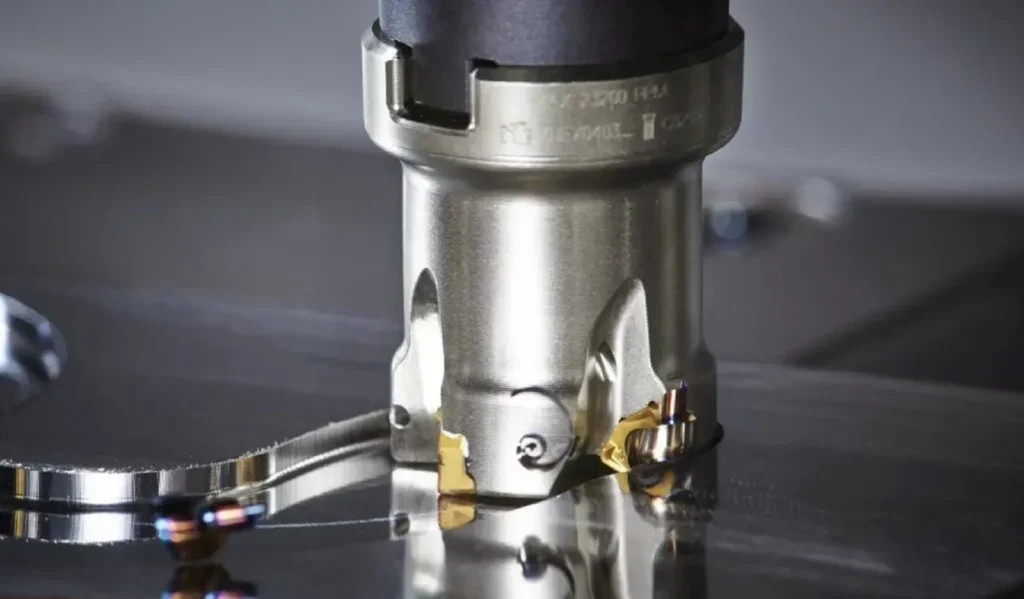
An indexable insert is a replaceable cutting element mechanically held in a toolholder or cutter body. When one cutting edge becomes worn, the insert can usually be rotated or flipped to present another usable edge instead of replacing the entire cutting tool.
Indexable inserts are widely used in turning, milling, drilling, boring, grooving, parting and threading systems. At ONMY Toolings, these applications are covered by dedicated product families including carbide turning inserts, milling inserts, threading tools, grooving tools and holemaking systems.
For a machinist or buyer, however, identifying an insert is only the beginning. Selecting the correct insert also requires matching:
- machining operation;
- workpiece material;
- insert shape;
- positive or negative geometry;
- chipbreaker;
- carbide grade;
- coating;
- corner radius;
- cutter or toolholder;
- cutting speed, feed and depth of cut.
This guide explains how these factors work together.
Indexable Inserts at a Glance
| Question | Quick answer |
|---|---|
| What is an indexable insert? | A replaceable cutting element mounted in a reusable toolholder or cutter body |
| What does “indexable” mean? | A worn cutting edge can normally be rotated or flipped to another usable edge |
| Where are indexable inserts used? | Turning, milling, drilling, boring, grooving, parting and threading |
| What are most inserts made from? | Cemented carbide is extremely common; cermet, ceramic, CBN and PCD are also used |
| Are all inserts interchangeable? | No. Shape, size, pocket, clamping method and dimensions must match |
| What determines chip control? | Cutting geometry together with feed, depth of cut and workpiece material |
| What determines wear resistance? | Primarily the cutting material, substrate and coating system |
| Does an ISO insert code tell you the grade? | No |
| Does an ISO code fully identify the chipbreaker? | No. Manufacturer geometry suffixes still need to be checked |
| Should I choose the insert without checking the holder? | No. Insert and holder or cutter body must form a compatible system |
What Is an Indexable Insert?
An indexable insert is a removable cutting tip seated in a precision pocket and secured mechanically by a screw, clamp, wedge, lever or another clamping system.
Unlike a brazed carbide cutting edge, the insert is not permanently attached to the tool body. When one cutting edge reaches the end of its useful life, the operator can index the insert to another available edge or replace it without replacing the complete holder.
For turning applications, the insert is normally mounted in a dedicated turning tool holder. Milling inserts are seated in rotating cutter bodies, while drilling inserts are mounted in indexable drill bodies.
What Does “Indexable” Mean in Machining?
In machining, indexing means repositioning an insert so that another usable cutting edge becomes active.
For example, a square insert may provide several usable corners. Once one corner becomes worn, the insert can be removed, rotated to the next valid position and clamped again.
However, the number of usable cutting edges is not determined by shape alone.
It also depends on:
- whether the insert is single-sided or double-sided;
- relief angle;
- chipbreaker configuration;
- cutter-pocket design;
- whether every corner can actually cut in that holder;
- special wiper or cutting-edge geometry.
Therefore:
Do not calculate insert cost only from the apparent number of corners. Confirm the number of usable edges for the complete insert and tool system.
Indexable Insert vs Replaceable-Tip Tool
These terms describe different tooling architectures.
An indexable insert normally has one or more cutting edges and fits into a reusable holder or cutter body.
A replaceable-tip or exchangeable-head tool uses a removable cutting head. When the head is worn, the complete head is replaced rather than indexed like a conventional insert.
Examples include:
- exchangeable drill heads;
- replaceable-tip end mills;
- modular boring heads;
- replaceable reaming heads.
Both systems reduce the need to discard the full tool assembly, but their interfaces and replacement methods are different.
How Indexable Cutting Tools Work
A typical indexable cutting system contains three main components.
1. Tool Body or Holder
The holder provides:
- rigidity;
- insert location;
- working cutting angle;
- coolant delivery;
- connection to the machine.
Examples include:
- external turning holders;
- boring bars;
- face milling cutters;
- shoulder milling cutters;
- indexable drills.
ONMY’s turning tool holder range includes holders for common insert families such as CNMG, CCMT, DCMT, DNMG, TNMG, VNMG and WNMG.
2. The Insert
The insert provides the cutting edge and contributes directly to:
- cutting-edge shape;
- chip formation;
- rake geometry;
- edge preparation;
- corner radius;
- cutting-material performance;
- wear resistance.
For example, a CNMG insert can be supplied with different chipbreakers and grades even though the same basic CNMG shape and size are retained.
3. Clamping and Locating System
The insert must sit consistently against the pocket locating surfaces.
Depending on the system, clamping can use:
- center screw;
- top clamp;
- wedge;
- lever;
- combination clamping.
Correct seating matters because even a correctly selected insert can perform poorly if:
- chips remain under the insert;
- the pocket is damaged;
- the screw is incorrect;
- the insert is not seated against its locating surfaces.
Types of Indexable Inserts
The term indexable insert covers several distinct product families.
Indexable Turning Inserts
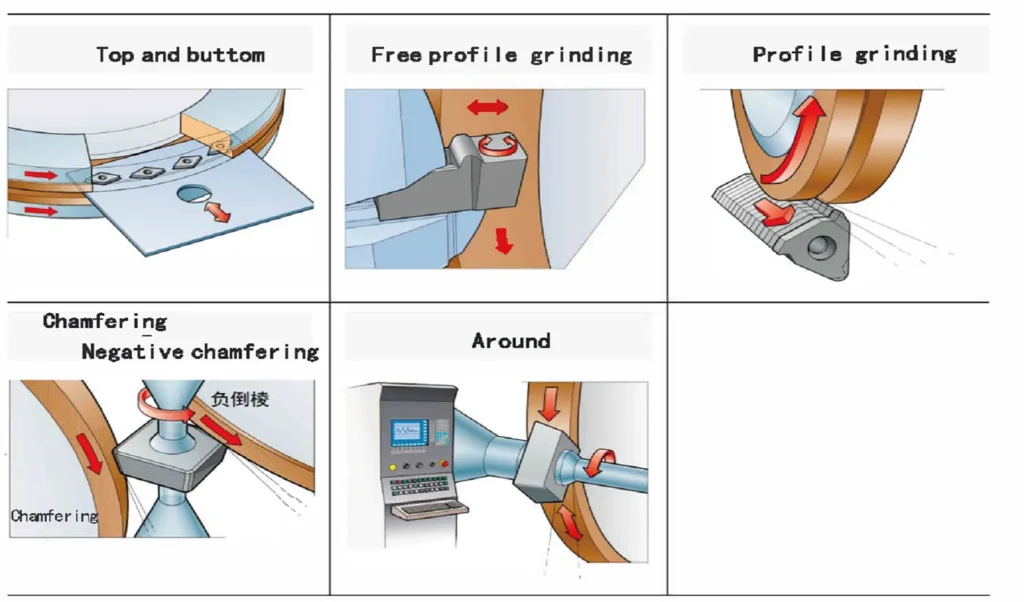
Turning inserts are used on conventional lathes and CNC turning centers.
Typical operations include:
- external turning;
- facing;
- internal turning;
- boring;
- profiling;
- chamfering.
Common families include:
You can view ONMY’s full carbide turning insert range to compare insert families by shape.
For a common example, see the dedicated CNMG insert guide and specifications.
Indexable Milling Inserts
Milling inserts are installed in rotating cutter bodies.
Typical applications include:
- face milling;
- shoulder milling;
- side milling;
- slot milling;
- high-feed milling;
- profile milling;
- pocketing;
- ramping;
- helical interpolation.
Unlike turning, milling is an interrupted cutting process. Each cutting edge repeatedly enters and exits the workpiece.
This means milling insert selection must consider:
- cutter entering angle;
- feed per tooth;
- axial depth of cut;
- radial engagement;
- impact at entry;
- thermal cycling;
- chip evacuation.
Browse the ONMY milling inserts range for application-specific milling insert families.
One common example is the APKT family. The dedicated APKT insert specifications and cutter compatibility guide explains APKT sizes and models.
Indexable Drilling Inserts
Indexable drills use replaceable cutting inserts mounted in a reusable drill body.
They are commonly selected where:
- hole diameter is relatively large;
- high metal-removal rate is required;
- replacing only the cutting elements is economical;
- one reusable drill body can cover repeated production.
Do not confuse conventional indexable drill inserts with exchangeable drill heads. ONMY’s holemaking range includes replaceable-tip and drilling tool systems.
Grooving and Parting Inserts
Grooving and parting inserts are relatively narrow cutting elements designed for:
- external grooves;
- internal grooves;
- face grooves;
- profiling;
- parting-off.
Important selection variables include:
- insert width;
- groove depth;
- holder rigidity;
- chip control;
- overhang;
- workpiece diameter.
For available systems, see grooving tools and insert holders.
Threading Inserts
Threading inserts generate a specified thread form.
They may be used for:
- ISO metric threads;
- UN threads;
- ACME threads;
- trapezoidal threads;
- API threads;
- Whitworth forms;
- partial-profile threads;
- full-profile threads.
The insert must match:
- thread standard;
- pitch;
- internal or external operation;
- right- or left-hand cutting;
- holder;
- workpiece material.
See ONMY’s threading tools, inserts and holders for the dedicated threading range.
Indexable Insert Shapes and Their Uses
Insert shape is not simply a naming convention.
The included angle has a major influence on two competing requirements:
cutting-edge strength and machining accessibility.
A larger included angle generally provides a stronger cutting corner, while a smaller included angle provides better access for profiling.
Common Insert Shapes
| Shape | Typical ISO letter | Main advantage | Main limitation | Typical use |
|---|---|---|---|---|
| Round | R | Very strong cutting edge | Limited access to sharp shoulders | Profiling and heavy cuts |
| Square | S | Strong corners and multiple edges | Limited profiling access | Roughing and milling |
| 80° diamond | C | Good strength/access balance | Cannot reach acute profiles | General turning |
| 80° trigon | W | Economical multi-edge design | Less access than D/V | General turning |
| Triangle | T | Multiple edges and good access | Lower strength than C/S | General machining |
| 55° diamond | D | Good profiling capability | Reduced corner strength | Profiling and finishing |
| 35° diamond | V | Excellent access | Relatively weak tip | Fine profiling |
| Parallelogram | A/K etc. | Application-specific geometry | Often cutter-specific | Milling applications |
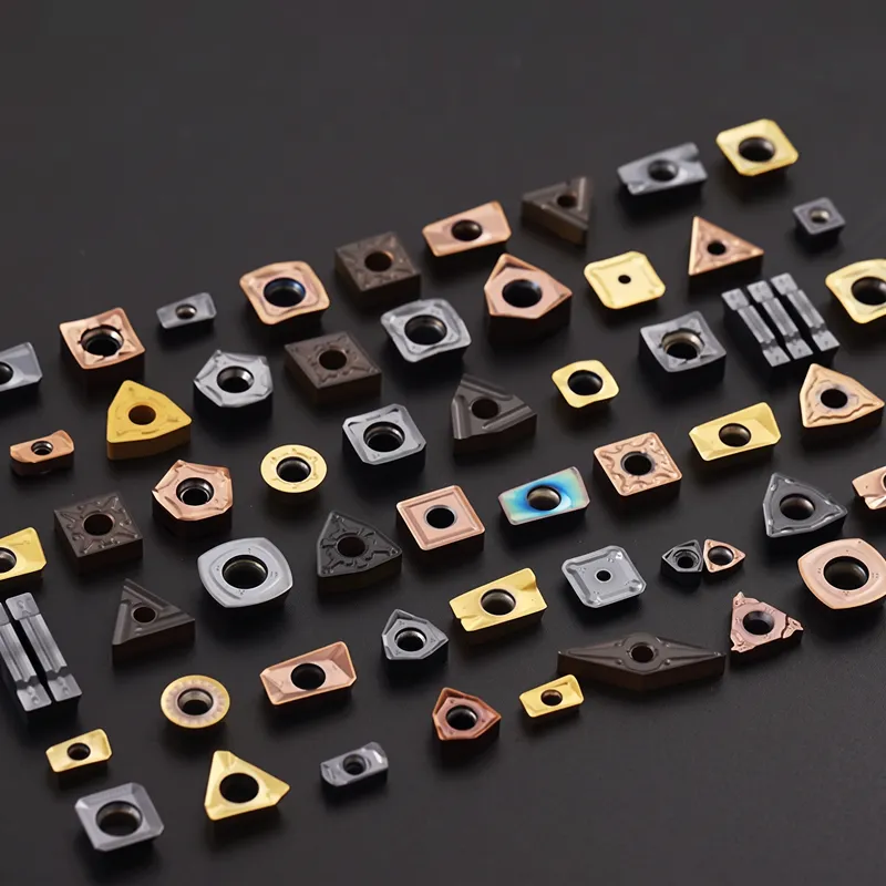
ONMY’s turning insert category is already organized by shapes including round, square, triangular, C-style, 55° and V-style inserts, which makes it useful when identifying an unknown turning insert.
The strongest insert shape is not automatically the best.
For heavy roughing, edge strength may dominate the decision.
For fine profiling around narrow features, accessibility can be more important.
Positive vs Negative Indexable Inserts
Another major selection decision is whether to use a positive-clearance or negative-style insert system.
Positive Inserts
Positive inserts provide clearance behind the cutting edge.
Typical advantages include:
- lower cutting forces;
- easier cutting action;
- reduced workpiece deflection;
- suitability for lower-power machines;
- good options for aluminum and other adhesive materials.
Possible tradeoffs include:
- less material supporting the cutting edge;
- often fewer usable sides;
- reduced edge strength in severe interrupted cutting.
Common positive families include CCMT and DCMT turning inserts as well as many APKT and APMT milling inserts.
Negative Inserts
Negative inserts commonly use a 0° basic clearance insert installed in a holder that creates the required working clearance.
Typical benefits include:
- strong cutting edge;
- potential for double-sided use;
- good cost per cutting edge;
- suitability for stable medium and rough machining.
Tradeoffs can include:
- higher cutting forces;
- higher machine-power requirements;
- greater tendency to deflect weak workpieces or setups.
CNMG is a common example. The ONMY CNMG insert uses an 80° rhombic basic shape with 0° clearance and is available with multiple geometries and grades.
How to Read an Indexable Insert Code
Standard indexable inserts commonly use ISO-style identification codes.
These codes make it easier to communicate important geometric and dimensional information, but they do not completely identify the cutting performance of the insert.
Consider:
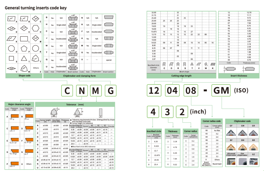
CNMG 120408
C — Shape
C represents an 80° diamond or rhombic insert shape.
N — Clearance Angle
N indicates 0° basic clearance.
M — Tolerance Class
M identifies the applicable dimensional tolerance class.
It does not mean:
- medium machining;
- carbide grade;
- coating;
- workpiece group.
G — Insert-Type Characteristics
The fourth position describes additional standardized insert features associated with the insert construction and clamping configuration.
It should not be interpreted as a universal manufacturer chipbreaker name.
12 — Size
For the common CNMG120408 example, 12 corresponds to a nominal inscribed-circle size of approximately 12.7 mm.
04 — Thickness Code
For this example, the nominal thickness is approximately 4.76 mm.
08 — Corner Radius
08 represents a nominal 0.8 mm nose radius.
The ONMY CNMG insert dimensions page lists common ISO examples including CNMG120404, CNMG120408 and CNMG120412.
What the ISO Code Does Not Tell You
CNMG120408 does not fully identify:
- carbide grade;
- coating system;
- chipbreaker;
- edge hone;
- finishing or roughing geometry;
- recommended workpiece material;
- cutting speed;
- feed range;
- depth-of-cut range.
That is why you should order using the complete manufacturer designation whenever possible.
Instead of sending only:
CNMG120408
send:
CNMG120408 + chipbreaker/geometry suffix + grade.
This dramatically reduces the chance of ordering a geometrically similar but functionally different insert.
Indexable Insert Materials
Indexable inserts can be produced from several cutting materials.
Cemented Carbide
Cemented carbide is the most common general-purpose material for modern indexable inserts.
It combines hard carbide particles with a metallic binder and may then receive:
- CVD coating;
- PVD coating;
- special surface treatments;
- edge preparation.
Carbide grades can be designed to provide different balances between:
- wear resistance;
- toughness;
- hot hardness;
- resistance to plastic deformation;
- resistance to chipping.
ONMY offers carbide inserts across both turning and milling applications.
Cermet
Cermets are frequently considered for finishing and semi-finishing applications where:
- wear resistance;
- chemical stability;
- consistent surface finish
are important.
They are particularly associated with steel finishing, although actual suitability depends on the grade and operation.
Ceramic
Ceramic inserts offer high hot hardness and wear resistance.
They can be useful for:
- selected cast irons;
- hardened materials;
- certain heat-resistant alloys.
However, ceramic tools usually require careful control of:
- cutting stability;
- interruption;
- machine rigidity;
- cutting parameters.
CBN / PCBN
Cubic boron nitride is primarily associated with hard turning and hardened ferrous materials.
If your application involves hardened steel, see ONMY’s dedicated CBN and PCBN insert range.
CBN selection must still consider whether the cut is:
- continuous;
- lightly interrupted;
- heavily interrupted;
- roughing;
- finishing.
PCD
Polycrystalline diamond is mainly used for selected non-ferrous and abrasive materials, such as:
- aluminum;
- high-silicon aluminum;
- copper alloys;
- composites.
If you are comparing cutting materials rather than insert shapes, see the detailed guide:
Cermet Inserts vs Carbide vs CBN vs PCD
Workpiece Material Groups: ISO P, M, K, N, S and H
A practical starting point for insert selection is the workpiece-material group.
| ISO group | Typical workpiece family | Common machining challenge |
|---|---|---|
| P | Steel | Wear, toughness and chip-control balance |
| M | Stainless steel | Work hardening, adhesion and long chips |
| K | Cast iron | Abrasion and edge wear |
| N | Non-ferrous materials | Adhesion, sharpness and sometimes abrasion |
| S | Titanium and heat-resistant alloys | Heat concentration and notch wear |
| H | Hardened materials | High hardness and abrasive wear |
The ISO group is only the beginning.
For example, “steel” may mean:
- low-carbon steel;
- medium-carbon steel;
- alloy steel;
- tool steel;
- hardened steel.
Likewise, stainless steel may be:
- austenitic;
- ferritic;
- martensitic;
- duplex;
- precipitation-hardening.
Whenever possible, provide the actual material designation and hardness when requesting an insert recommendation.

Grade vs Geometry vs Coating
These three terms are often confused.
| Feature | Primarily influences |
|---|---|
| Basic insert shape | Edge strength and accessibility |
| Geometry / chipbreaker | Chip formation, cutting forces and edge strength |
| Edge preparation | Sharpness and resistance to microchipping |
| Grade | Wear resistance, toughness and heat resistance |
| Coating | Friction, heat protection and wear behavior |
| Corner radius | Strength, surface finish and cutting pressure |
| Insert size | Cutting capacity and holder compatibility |
Insert Geometry
Geometry describes how the cutting edge mechanically interacts with the workpiece.
It includes:
- rake angle;
- chipbreaker;
- edge land;
- edge hone;
- cutting-edge preparation.
A finishing geometry may prioritize:
- sharpness;
- low cutting force;
- chip control at light cuts.
A roughing geometry may prioritize:
- reinforced edge;
- strength;
- chip space;
- heavy feed and depth of cut.
Insert Grade
The grade describes the cutting-material system.
For carbide this can include:
- carbide substrate;
- grain structure;
- binder content;
- coating;
- post-treatment.
A harder grade is not automatically better.
Stable finishing may benefit from a highly wear-resistant grade.
Interrupted cutting may require a tougher grade.
Coating
Common carbide insert coating technologies include:
- PVD;
- CVD;
- multilayer coating systems;
- low-friction coatings for selected non-ferrous applications.
Never select an insert grade only from coating color.
What Is an Insert Chipbreaker?
A chipbreaker is part of the cutting-edge geometry and influences:
- chip flow;
- chip curling;
- chip breaking;
- cutting force;
- edge strength.
A finishing chipbreaker typically works at lower feed and depth of cut.
A roughing geometry normally uses a stronger edge and is designed for higher loads.
However, chipbreaker suffixes are usually manufacturer-specific.
Therefore:
A geometry called “M” by one manufacturer should not automatically be treated as equivalent to an “M” geometry from another manufacturer.
ONMY’s CNMG insert range is a good example: the same basic CNMG family can be combined with different chipbreakers and grades for different machining conditions.
How to Choose the Right Indexable Insert
The correct question is not:
“Which carbide insert is best?”
The useful question is:
Which insert matches this operation, material, holder, machine and cutting condition?
Use the following sequence.
Step 1: Identify the Operation
First determine whether the operation is:
- external turning;
- facing;
- boring;
- profiling;
- face milling;
- shoulder milling;
- slot milling;
- high-feed milling;
- drilling;
- grooving;
- parting;
- threading.
Start from the relevant product family:
- Turning Inserts
- Milling Inserts
- Threading Tools
- Grooving Tools
Do not select an insert only because its visible shape resembles the old insert.
Step 2: Identify the Exact Workpiece Material
Instead of:
steel
provide:
AISI 4140, 28–32 HRC.
Instead of:
stainless steel
provide:
Instead of:
titanium
provide:
Ti-6Al-4V.
Exact alloy and hardness strongly influence grade, geometry and cutting parameters.
Step 3: Choose the Insert Shape
If maximum cutting-edge strength is important, consider shapes with larger included angles.
If profile access is important, smaller-angle diamond shapes may be more suitable.
For turning, the carbide turning insert category allows you to compare common K, W, R, T, S, V, D and C-style insert families.
Step 4: Choose Positive or Negative Geometry
Positive geometries are often useful where you need:
- low cutting force;
- thin-wall machining;
- smaller machine power;
- sharp cutting action.
Negative systems are often selected where you need:
- strong edges;
- stable heavy cutting;
- economical double-sided inserts.
The holder must match the insert style. See the turning tool holder range when checking turning-insert compatibility.
Step 5: Select the Chipbreaker
Determine whether the operation is:
- finishing;
- semi-finishing;
- medium machining;
- roughing;
- heavy roughing.
Then compare:
- feed;
- depth of cut;
- workpiece material;
- continuous or interrupted engagement.
A finishing chipbreaker used in heavy roughing may fail from insufficient edge strength.
A heavy roughing geometry used for a very light finishing cut may produce excessive cutting force or poor chip control.
Step 6: Select the Grade
Choose the grade according to:
- workpiece material;
- cutting speed;
- machining stability;
- continuous or interrupted cut;
- coolant;
- required tool life.
If carbide is no longer the best cutting material, compare carbide, cermet, CBN and PCD inserts.
For hardened-steel applications specifically, review the CBN insert range.
Step 7: Select the Corner Radius
A larger corner radius generally provides more mechanical corner strength.
However, it also influences:
- radial cutting force;
- chatter tendency;
- minimum practical depth of cut;
- surface finish.
A smaller radius reduces cutting pressure but provides less corner strength.
Step 8: Confirm Holder or Cutter Compatibility
Always check:
- insert family;
- size;
- thickness;
- hole;
- countersink;
- pocket geometry;
- clamping method;
- screw;
- hand;
- radius clearance.
A similar size code does not prove interchangeability.
This is particularly important in milling. For example, APKT and APMT can appear very similar while still requiring verification of tolerance, dimensions and cutter-pocket compatibility.
Read:
APMT vs APKT: What Is the Difference?
You can also check the dedicated APKT insert specifications when identifying an APKT milling insert.
Step 9: Set Cutting Conditions
Confirm:
- cutting speed, Vc or SFM;
- feed per revolution, fn, for turning;
- feed per tooth, fz, for milling;
- axial depth of cut, ap;
- radial engagement, ae, for milling;
- coolant;
- machine power;
- tool overhang;
- workholding rigidity.
Changing insert geometry without checking cutting conditions may not solve the actual problem.
Step 10: Inspect the Result
After the first controlled test, inspect:
- chip shape;
- spindle load;
- surface finish;
- flank wear;
- crater wear;
- chipping;
- built-up edge;
- notch wear;
- insert seating;
- dimensional stability.
The catalog recommendation is the starting point.
The final cutting condition must be validated on the actual machine and workpiece.
Finishing, Medium and Roughing Inserts
One insert family may have several geometries.
Finishing Inserts
A finishing geometry generally prioritizes:
- sharp cutting action;
- lower forces;
- chip control at light feed;
- surface quality.
Typical applications include:
- small depths of cut;
- lower feed;
- precision finishing;
- thin or weak workpieces.
Medium Machining Inserts
Medium geometries aim for a balance of:
- edge strength;
- chip control;
- cutting force;
- operating range.
They are commonly a good starting direction for stable general-purpose machining.
Roughing Inserts
Roughing geometries prioritize:
- strong cutting edge;
- larger chip capacity;
- higher feed;
- deeper cuts;
- resistance to heavy load.
They may create substantially higher cutting forces than a finishing geometry.
Indexable Inserts vs Solid Carbide Tools
Neither system is universally better.
They solve different machining problems.
| Factor | Indexable tooling | Solid carbide tooling |
|---|---|---|
| Cutting edge | Replaceable insert | Integral with tool |
| Tool body | Reusable | Tool itself |
| Worn edge | Index or replace insert | Replace or regrind tool |
| Large cutter diameter | Strong advantage | Can become expensive |
| Small diameter | Limited by insert and pocket | Strong advantage |
| Heavy roughing | Excellent application | Application-dependent |
| Fine small features | Limited by insert size | Often excellent |
| Grade flexibility | Change insert grade easily | Requires another tool |
| Geometry flexibility | Change compatible insert | Requires different tool |
| Runout | Depends on pocket and seating | No insert-pocket interface |
ONMY sells both indexable milling systems through its milling insert range and solid carbide tools through its carbide end mill product families.
When Indexable Tooling Is Attractive
Consider indexable tooling when:
- cutter diameter is relatively large;
- metal-removal rate is important;
- cutting edges are replaced frequently;
- several grades or geometries may be required;
- a reusable cutter body improves economics.
When Solid Carbide May Be Better
Solid carbide is often worth considering when:
- diameter is too small for an insert pocket;
- very fine features are required;
- very low runout is important;
- long reach is required;
- continuous flute geometry offers an advantage.
For example, ONMY’s solid carbide ball nose end mills are intended for applications such as 3D contouring and mold finishing where a solid tool may be preferable to a larger indexable cutter.
Advantages of Indexable Inserts
Multiple Usable Cutting Edges
Many insert designs provide several usable edges, reducing the cost per cutting edge.
Fast Replacement
A worn insert can be indexed or replaced without changing the entire holder or cutter body.
Application Flexibility
One compatible tooling platform may accept different:
- grades;
- chipbreakers;
- corner radii;
- geometries.
Specialized Cutting Materials
Indexable systems can use:
- carbide;
- cermet;
- ceramic;
- CBN;
- PCD.
Production Efficiency
Predictable insert replacement is particularly valuable in CNC production where reducing downtime is important.
Limitations of Indexable Inserts
Indexable tooling also has limitations.
Inserts Are Not Universal
Similar-looking inserts may not fit the same holder.
Pocket Condition Matters
Damaged or contaminated pockets can cause:
- runout;
- vibration;
- screw failure;
- premature edge failure;
- inconsistent dimensions.
Some Geometries Generate High Cutting Forces
Strong negative inserts may require more machine power and rigidity than sharp positive inserts.
Small Diameters Are Limited
A small tool may not have enough space for:
- an insert pocket;
- screw;
- strong cutter core;
- sufficient chip space.
Lowest Insert Price Does Not Equal Lowest Machining Cost
A cheap insert that causes:
- lower productivity;
- frequent indexing;
- poor finish;
- rework;
- machine stops
may cost more per finished part.
Evaluate:
cost per usable edge and cost per finished component, not only purchase price.
Common Indexable Insert Selection Mistakes
Mistake 1: Ordering Only by Shape
“80-degree diamond insert” is not enough.
You still need:
- size;
- thickness;
- radius;
- clearance;
- hole;
- chipbreaker;
- grade.
Mistake 2: Ordering Only by ISO Base Code
CNMG120408 is incomplete if several geometries and grades are available.
Use the complete code whenever possible.
Mistake 3: Confusing Grade and Chipbreaker
They perform different jobs.
Geometry influences how the edge cuts.
Grade influences how the cutting material survives wear, heat and load.
Mistake 4: Choosing the Hardest Grade
Maximum hardness can reduce toughness.
Interrupted or unstable cuts may require a tougher grade.
Mistake 5: Choosing the Strongest Geometry
A heavily reinforced roughing geometry may create excessive cutting forces in:
- finishing;
- thin-wall parts;
- small machines;
- unstable setups.
Mistake 6: Ignoring the Holder
The insert and holder form one system.
For turning, verify the relevant turning tool holder before purchasing replacement inserts.
Mistake 7: Selecting by Coating Color
Similar-looking coatings may use completely different systems.
Use the grade designation and manufacturer data rather than visual appearance.
Mistake 8: Assuming Manufacturer Suffixes Are Universal
One manufacturer’s chipbreaker suffix does not necessarily equal another manufacturer’s geometry with the same letter.
How to Identify an Unknown Indexable Insert
If the original box or complete designation is missing, use this process.
1. Read Every Marking
Photograph both sides and record:
- letters;
- numbers;
- manufacturer logo;
- geometry code;
- grade marking.
2. Identify the Basic Shape
Determine whether the insert is:
- round;
- square;
- triangular;
- C style;
- W style;
- D style;
- V style;
- parallelogram;
- another special shape.
The carbide turning insert overview is useful for visually narrowing down common turning insert families.
3. Measure Critical Dimensions
Depending on the insert, measure:
- inscribed circle;
- cutting-edge length;
- thickness;
- hole diameter;
- corner radius;
- overall length;
- width.
4. Identify the Holder or Cutter
Photograph:
- insert pocket;
- screw;
- cutter body;
- holder markings.
For turning applications, compare the holder with ONMY’s turning tool holder families.
5. Provide the Machining Application
Include:
- material;
- operation;
- speed;
- feed;
- depth of cut;
- coolant;
- current machining problem.
6. Never Force a Similar Insert Into the Pocket
Stop if the insert:
- rocks;
- does not sit flat;
- requires excessive screw force;
- leaves a visible gap;
- contacts only part of the locating surface.
A near match is not necessarily a compatible insert.
What Information Should You Send for an Insert Recommendation?
For faster insert matching, provide the following information.
Existing Tooling
- complete insert designation;
- manufacturer;
- toolholder or cutter code;
- photos of the insert;
- photos of the insert pocket.
Workpiece
- material standard;
- exact grade;
- hardness;
- heat-treatment condition.
Machining Operation
- turning;
- milling;
- drilling;
- threading;
- grooving;
- roughing;
- finishing;
- continuous or interrupted cutting.
Cutting Conditions
- cutting speed;
- feed;
- depth of cut;
- radial engagement for milling;
- coolant condition.
Machine and Setup
- machine type;
- spindle power;
- tool overhang;
- workholding;
- rigidity limitations.
Current Problem
- short tool life;
- chipping;
- long chips;
- built-up edge;
- poor surface finish;
- chatter;
- excessive wear;
- insert breakage.
If you need help identifying an unknown insert or finding an equivalent, send your tooling requirement to ONMY with the complete code, photos and machining information.
Frequently Asked Questions
What is an indexable insert?
An indexable insert is a replaceable cutting element installed in a reusable toolholder or cutter body. When one cutting edge wears, the insert can usually be rotated or replaced without discarding the complete tool.
What does indexable mean in machining?
Indexable means the insert can be repositioned so that another usable cutting edge becomes active.
What are indexable inserts used for?
They are used for turning, milling, drilling, boring, threading, grooving and parting.
ONMY groups these applications into dedicated turning insert, milling insert, threading and grooving product families.
What are indexable inserts made from?
Cemented carbide is extremely common.
Other cutting materials include:
- cermet;
- ceramic;
- CBN;
- PCD.
For a detailed comparison, read Cermet Inserts vs Carbide vs CBN vs PCD.
Are carbide inserts and indexable inserts the same?
Not exactly.
Indexable describes the tooling concept.
Carbide describes the cutting material.
Many indexable inserts are made from carbide, but an indexable insert may also be cermet, ceramic, CBN or PCD.
Are indexable inserts universal?
No.
The insert must match the holder or cutter in:
- shape;
- size;
- thickness;
- hole;
- seating surface;
- clamping system;
- cutting-edge position.
Never assume interchangeability from appearance alone.
How do I read an indexable insert code?
The standard code identifies important features such as:
- shape;
- clearance;
- tolerance;
- insert type;
- size;
- thickness;
- corner radius.
However, grade and manufacturer-specific cutting geometry still need to be identified separately.
For a practical example, see the CNMG120408 dimensions and code information.
What is the difference between insert geometry and insert grade?
Geometry determines how the cutting edge interacts with the material.
Grade determines how the cutting material resists:
- wear;
- heat;
- fracture.
They must be selected together.
What is the difference between a chipbreaker and a coating?
A chipbreaker is part of the physical cutting-edge geometry.
A coating is a surface layer designed to influence wear, friction, temperature and material interaction.
Which insert shape is strongest?
Round and large-included-angle shapes generally provide strong cutting edges, but the strongest insert may not provide sufficient access for profiling.
Which insert is best for finishing?
Use a finishing geometry and grade designed for the specific:
- workpiece;
- feed;
- depth of cut;
- stability;
- required surface finish.
There is no universal “best finishing insert.”
Which insert is best for roughing?
Use a reinforced geometry and suitable grade capable of handling the required:
- feed;
- depth of cut;
- impact;
- heat;
- machine load.
How do I choose an insert for stainless steel?
First identify the exact stainless grade.
Then select:
- material-appropriate grade;
- suitable chipbreaker;
- adequate edge strength;
- appropriate cutting conditions.
For turning applications, begin with the carbide turning insert range and provide the stainless grade when requesting a recommendation.
Can I replace one manufacturer’s insert with another brand?
Sometimes, but the ISO base designation alone is not enough.
Compare:
- dimensions;
- chipbreaker;
- grade;
- edge preparation;
- usable edges;
- holder compatibility;
- recommended cutting range.
Can APKT replace APMT?
Do not assume interchangeability from the similar code.
Read the dedicated APMT vs APKT comparison and confirm the complete dimensions and cutter pocket before substitution.
When should I use CBN instead of carbide?
CBN is commonly considered for hardened ferrous materials where carbide tool life or cutting speed becomes limiting.
See ONMY’s CBN and PCBN inserts for hard-turning options.
When should I use indexable tooling instead of solid carbide?
Indexable tooling is especially attractive when:
- reusable tool bodies are economical;
- cutting diameter is relatively large;
- high metal-removal rate is required;
- rapid edge replacement is valuable.
Solid carbide often has advantages in smaller diameters, fine features and applications where an insert pocket is impractical.
Final Indexable Insert Selection Checklist
Before ordering an indexable insert, confirm:
- machining operation;
- workpiece material;
- material hardness;
- holder or cutter designation;
- insert shape;
- insert size;
- positive or negative geometry;
- chipbreaker;
- insert grade;
- coating;
- corner radius;
- finishing, medium or roughing requirement;
- cutting speed;
- feed;
- depth of cut;
- coolant condition;
- continuous or interrupted engagement;
- machine rigidity;
- workholding stability.
Successful insert selection is rarely determined by one specification.
The best result comes from treating the:
insert + geometry + grade + holder + workpiece + cutting conditions
as one complete machining system.
If you are replacing an existing insert, send the complete insert designation, holder or cutter model, workpiece material, cutting parameters and clear photos rather than selecting a replacement from shape alone.