Carbide inserts are manufactured through a precision powder metallurgy process that transforms micron-scale tungsten carbide (WC) powder and a metallic binder—typically cobalt (Co)—into dense, ultra-hard cutting tools. The industrial production route involves raw material preparation, wet ball milling, spray drying, die pressing, debinding, liquid-phase sintering, precision diamond grinding, cutting edge preparation, and CVD or PVD surface coating.
Each manufacturing stage directly governs the insert’s final hardness, transverse rupture strength (TRS), fracture toughness, dimensional tolerance, and tool life. This engineering guide explains the material composition of cemented carbide, how tungsten carbide powder is synthesized, the 10-step insert manufacturing workflow, and how quality is controlled from raw powder to finished cutting edge.
1. What Are Carbide Inserts Made Of?
Before examining how carbide inserts are manufactured, it is essential to understand their metallurgical composition. Conventional cemented carbide cutting inserts are composite materials composed of hard carbide particles bonded together by a ductile metallic binder phase.
1.1 Tungsten Carbide Powder (WC)
Tungsten carbide serves as the primary hard phase, typically accounting for 70% to 97% of the total weight depending on the grade. It provides:
- Extreme hardness and hot hardness (red hardness)
- High abrasion and crater wear resistance
- Exceptional compressive strength and rigidity
- Thermal stability under high-speed cutting temperatures
Both the average WC grain size (ranging from sub-micron and ultra-fine < 0.5 μm up to coarse > 3.0 μm) and grain size distribution are critical variables that dictate the final balance between wear resistance and edge toughness.
1.2 Cobalt Binder (Co)
Cobalt acts as the liquid-phase sintering aid and metallic matrix that binds tungsten carbide grains together. Its proportion governs the fundamental trade-off between hardness and toughness:
- Higher cobalt content (e.g., 10%–15%+): Increases fracture toughness and impact resistance, making the grade suitable for heavy interrupted cuts, roughing, or unstable setups.
- Lower cobalt content (e.g., 3%–8%): Increases hardness and abrasion resistance, favoring high-speed continuous finishing and cast iron or non-ferrous machining.
Because different workpiece materials and cutting operations impose different mechanical and thermal loads, manufacturers formulate specific binder contents for each ISO application range (P, M, K, N, S, H).
1.3 Cubic Carbides and Grain Growth Inhibitors
To tailor performance for high-temperature steel machining or ultra-fine microstructures, formulations frequently incorporate secondary carbides:
- Titanium carbide (TiC): Improves crater wear resistance and chemical stability at elevated cutting temperatures.
- Tantalum carbide (TaC) and Niobium carbide (NbC): Enhance thermal shock resistance, hot strength, and resistance to plastic deformation.
- Vanadium carbide (VC) and Chromium carbide (Cr₃C₂): Act as potent grain growth inhibitors during sintering, keeping WC grains fine and uniform while improving corrosion and oxidation resistance.
2. How Is Tungsten Carbide Powder Made?
A common technical question is how raw tungsten ore becomes tungsten carbide powder prior to insert production. Tungsten carbide powder synthesis and carbide insert manufacturing are two distinct industrial stages; most insert manufacturers source certified WC powder from specialized metallurgical refineries.
Industrial WC powder production typically relies on a two-step high-temperature chemical process:
Step 1: Hydrogen Reduction of Tungsten Oxide
High-purity tungsten trioxide (WO₃) or ammonium paratungstate (APT) derivatives are reduced in a flowing hydrogen atmosphere at controlled temperatures (typically 700°C to 900°C) to yield pure metallic tungsten (W) powder:
WO₃ + 3H₂ → W + 3H₂O
Step 2: High-Temperature Carburization
The metallic tungsten powder is blended with high-purity carbon black and heated in a carburizing furnace between 1,400°C and 1,600°C to form stoichiometric tungsten carbide (WC):
W + C → WC
Step 3: WC Powder Classification and Inspection
Before entering cemented carbide batching, the synthesized WC powder is de-agglomerated, sieved, and evaluated for:
- Fisher Sub-Sieve Sizer (FSSS) particle size and laser diffraction distribution
- Total carbon content (typically ~6.13 wt% theoretical) and free carbon levels
- Oxygen, iron, and trace impurity levels
- Powder morphology and bulk apparent density
3. How Are Carbide Inserts Made? The Manufacturing Process
Once raw powders are verified, cemented carbide inserts are produced through the following sequential workflow:
From micron-scale tungsten carbide powder to precision-ground and coated cutting tools
Precision formulation of WC powder, cobalt binder, and cubic carbide additives.
Slurry milling in organic solvent to coat WC grains evenly with Co and pressing wax.
Atomizing wet slurry in heated nitrogen to form spherical, free-flowing granules.
Compacting granules in CNC dies to form fragile green compacts with 3D chipbreakers.
Controlled thermal extraction of paraffin/PEG lubricants to preserve carbon balance.
Vacuum liquid-phase sintering with high-pressure Argon to eliminate internal pores.
Multi-axis CNC diamond wheel grinding for seating faces, periphery, and wiper radii.
Engineering micro-geometry via brush honing or micro-blasting to prevent chipping.
Depositing thermal and wear-resistant surface layers after ultrasonic cleaning.
Verifying hardness, microstructure, edge profile, and coating adhesion before laser marking.
3.1 Raw Material Preparation and Batching
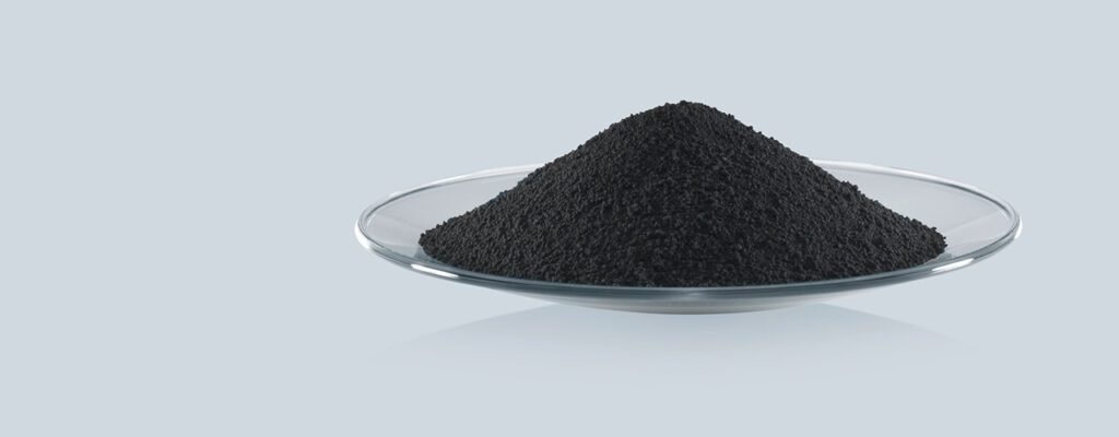
Production begins by weighing tungsten carbide powder, cobalt powder, cubic carbides (TiC, TaC, NbC), and grain growth inhibitors according to a proprietary grade recipe. Because a carbon deviation of even 0.05% can trigger brittle eta-phase (η-phase) or free graphite defects during sintering, raw material weighing is strictly controlled with automated precision scales and full batch traceability.
3.2 Wet Mixing and Ball Milling
The weighed powders are loaded into carbide-lined rotary ball mills or vertical attritor mills along with cemented carbide milling media (balls).
- Liquid Milling Medium: An organic solvent—such as ethanol, acetone, or heptane—is added to prevent oxidation, dissipate heat, and ensure homogeneous dispersion.
- Pressing Lubricant Addition: Organic pressing aids, typically paraffin wax or polyethylene glycol (PEG) at 1.5% to 2.5% by weight, are dissolved into the slurry to coat the powder particles and facilitate subsequent die compaction.
- Process Control: Milling duration (often 12 to 48+ hours) and rotational speed are tightly monitored to de-agglomerate particles, coat every WC grain evenly with cobalt, and achieve the target particle size distribution without over-milling.
3.3 Spray Drying and Granulation
Raw milled carbide powder is cohesive and flows poorly, making it impossible to fill intricate pressing dies uniformly. To solve this, the wet slurry is pumped into a closed-loop nitrogen spray dryer.
- Atomizer nozzles spray the slurry into droplets inside a heated drying tower.
- The organic solvent evaporates rapidly and is recovered via condensation.
- The remaining WC-Co particles and wax binder agglomerate into spherical, free-flowing granules (typically 50 to 200 μm in diameter).
These uniform spherical granules ensure rapid, consistent die filling and repeatable press density.
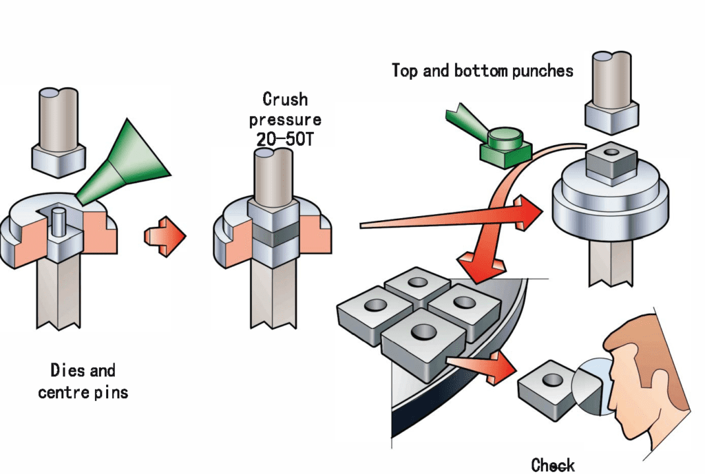
3.4 Pressing and Shaping (Green Compaction)
The granulated powder is fed into high-precision CNC mechanical, hydraulic, or electric multi-axis presses equipped with tungsten carbide/steel dies and core rods.
- Compaction Pressure: The powder is compressed under pressures typically ranging from 100 to 300 MPa, forming a green compact.
- Molding Complex Chipbreakers: Top and bottom punches mold the 3D chipbreaker geometry, central mounting hole, and clearance angles directly into the green compact.
- Shrinkage Allowance: Because the green compact has chalk-like fragility and roughly 45%–50% porosity, the pressing die must be engineered approximately 20% to 25% larger than the final insert dimensions to compensate for sintering shrinkage.
3.5 Debinding (Dewaxing) and Pre-Sintering
Before high-temperature densification, the 1.5%–2.5% paraffin wax or PEG pressing lubricant must be completely extracted.
- The green compacts are heated slowly in a controlled hydrogen or vacuum atmosphere between 200°C and 500°C.
- The wax vaporizes and is swept out of the furnace chamber into a condenser trap.
- If semi-finished shaping (green machining) is required for complex non-standard tools, compacts may undergo a pre-sintering stage at 700°C–900°C to impart sufficient handling strength before final sintering.
3.6 Liquid-Phase Sintering
Sintering is the core metallurgical transformation that converts a fragile green compact into a dense, ultra-hard cutting tool.
- Temperature & Cycle: The debound compacts are heated in a vacuum furnace to 1,350°C–1,500°C (depending on cobalt content) for a complete furnace cycle lasting 12 to 24+ hours.
- Liquid Phase & Capillary Action: Above ~1,320°C (the WC-Co eutectic temperature), the solid cobalt binder melts into a liquid phase. Driven by surface tension and capillary forces, liquid cobalt wets and pulls the solid WC grains tightly together, dissolving fine carbide edges and re-precipitating them into an interlocking skeletal structure.
- Densification & Shrinkage: Internal pores collapse, bringing theoretical density to nearly 100%. During this process, the insert undergoes 18% to 25% linear shrinkage (around 40% to 50% volume reduction).
3.7 Sinter-HIP / Hot Isostatic Pressing (HIP)
To eliminate trace residual micro-porosity that could act as fracture initiation sites under heavy interrupted cutting, manufacturers utilize Sinter-HIP technology.
- During the peak liquid-phase sintering hold, the furnace is pressurized with high-purity inert Argon gas at 30 to 100 bar (3 to 10 MPa).
- The isotropic gas pressure collapses internal voids, maximizing transverse rupture strength (TRS) and batch-to-batch reliability without requiring a separate post-sintering thermal cycle.
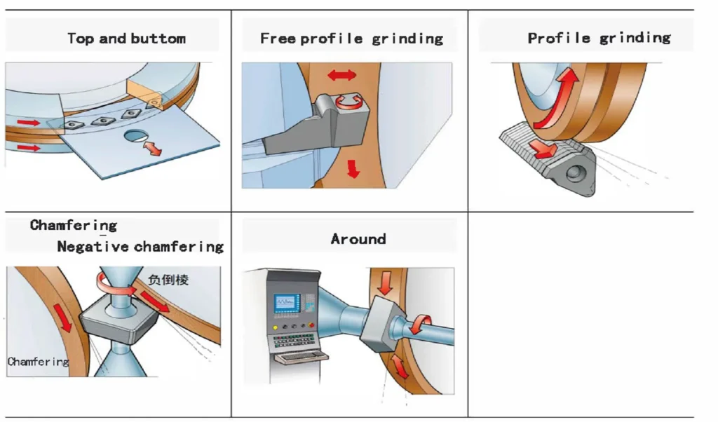
3.8 Precision Diamond Grinding and Finishing
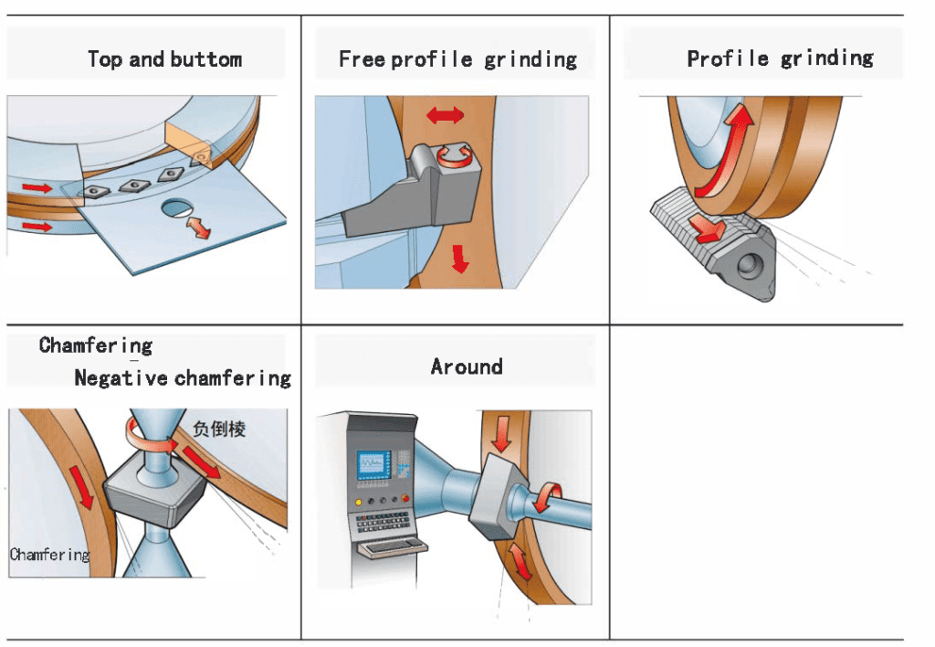
Because sintered cemented carbide ranks between 88 and 94 HRA (1,300 to 2,000+ HV), conventional abrasives cannot cut it. Multi-axis CNC grinding machines equipped with metal- or resin-bonded diamond grinding wheels are used to achieve final geometric tolerances.
- M-Class (Pressed-to-Size) Inserts: Standard utility inserts often require only top and bottom seating face grinding to ensure flatness and thickness accuracy, while preserving the as-sintered peripheral edge and chipbreaker.
- G-Class and E-Class (Precision Ground) Inserts: Close-tolerance turning inserts, threading inserts, grooving tools, and wiper geometries undergo full peripheral profile grinding, corner radius (R-angle) grinding, and seating surface finishing to achieve tolerances as tight as ±0.025 mm or ±0.005 mm.
3.9 Cutting Edge Preparation (Honing & Chamfering)
A freshly sintered or diamond-ground carbide edge is microscopically jagged and overly brittle for most machining operations. Cutting edge preparation applies a controlled micro-geometry via brush honing, abrasive blasting, or drag finishing to prevent premature micro-chipping:
- Up-Sharp (S-Edge): Unhoned, razor-sharp edge designed to minimize cutting forces and built-up edge (BUE) when machining aluminum, plastics, or gummy wrought alloys.
- Honed / Rounded (E-Edge): Symmetrical round hone (typically R0.02 mm to R0.08 mm) or Waterfall (elliptical) hone (e.g., 2:1 ratio) that strengthens the cutting edge for general steel, stainless steel, and cast iron turning or milling.
- Chamfered / T-Land (T-Edge): A negative flat land (e.g., 0.10–0.30 mm wide at 15°–25°) that redirects cutting forces into compressive stress, used for heavy roughing, interrupted cuts, and hardened steel machining.
- Chamfered + Honed (S-Edge): Combines a negative T-land with a rounded transition radius for extreme impact resistance.
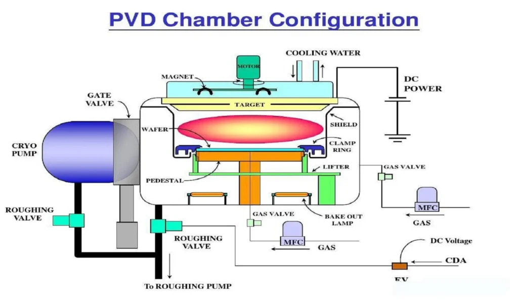
3.10 CVD and PVD Surface Coating – Optional
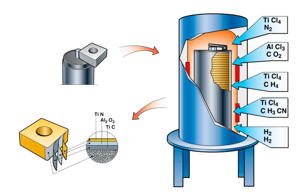
Before coating, inserts undergo ultrasonic chemical cleaning and micro-blasting to ensure immaculate substrate cleanliness. Over 80% of modern indexable carbide inserts receive either a Chemical Vapor Deposition (CVD) or Physical Vapor Deposition (PVD) coating.
CVD Coating (Chemical Vapor Deposition)
- Process Temperature: ~800°C to 1,050°C
- Typical Thickness: 5 to 20 μm
- Common Multi-Layer Architecture: TiN + MT-TiCN (Medium-Temperature Titanium Carbonitride) + α-Al₂O₃ (Alpha Aluminum Oxide) + outer indicator layer (TiN or ZrCN).
- Primary Advantage: Thick, chemically stable thermal barrier with superior crater and flank wear resistance; ideal for high-speed continuous turning and heavy roughing of steels and cast irons.
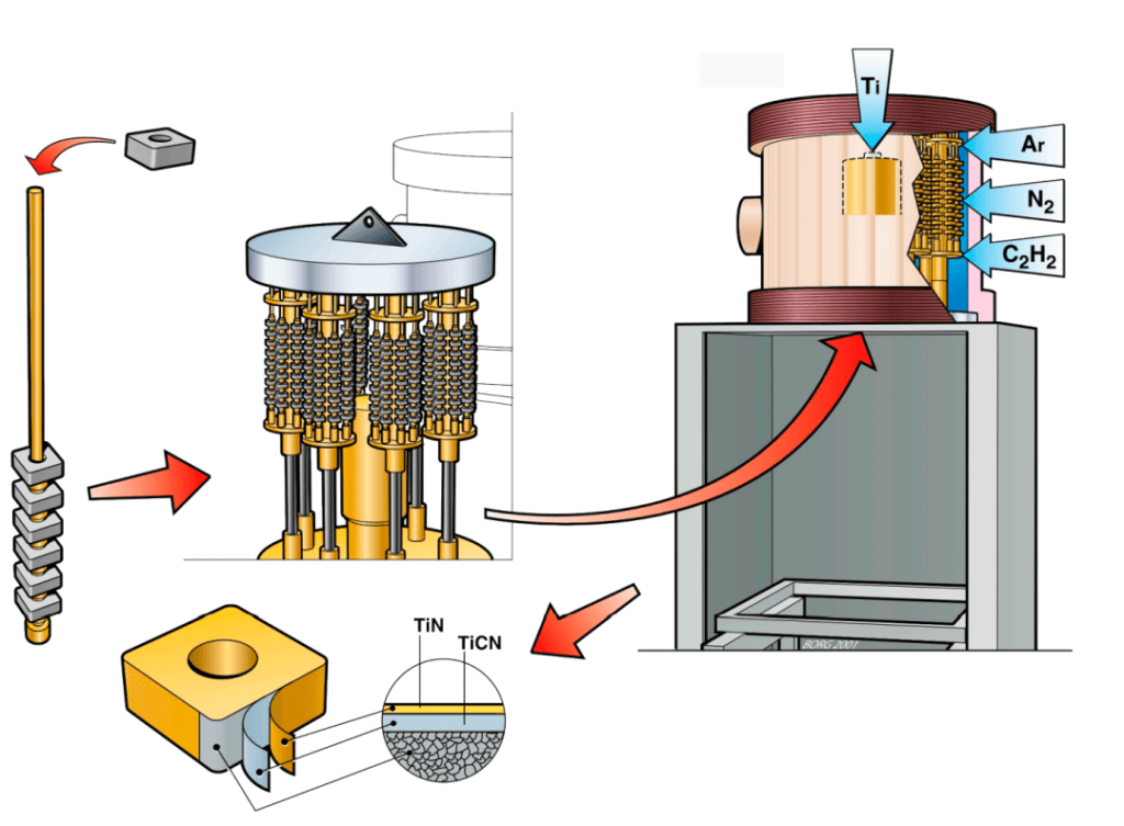
PVD Coating (Physical Vapor Deposition)
- Process Temperature: ~400°C to 600°C (arc evaporation or magnetron sputtering)
- Typical Thickness: 1 to 5 μm
- Common Coating Materials: TiAlN, AlTiN, AlCrN, TiN, TiCN, and nano-composite multilayers.
- Primary Advantage: Lower process temperature avoids thermal degradation (eta-phase formation) of the substrate, retains beneficial compressive stress, and preserves sharp cutting edges—making PVD ideal for milling, drilling, threading, grooving, and heat-resistant superalloy (HRSA) machining.
4. Quality Control in Carbide Insert Manufacturing
A carbide insert with the correct external dimensions can still fail catastrophically on the shop floor if its internal microstructure, carbon balance, or edge micro-geometry is out of specification. Comprehensive quality assurance spans metallurgical lab testing and finished-part metrology:
4.1 Raw Material & Powder Lot Verification
Incoming WC and Co powders are tested for chemical purity, total and free carbon content, oxygen content, particle size distribution, and apparent density prior to batching.
4.2 Density and Magnetic Properties Testing
- Archimedes Density: Verifies full densification after Sinter-HIP (typically 11.0 to 15.2 g/cm³ depending on Co and cubic carbide content).
- Magnetic Saturation (Co-Mag) & Coercivity (Hc): Non-destructive electromagnetic tests that rapidly verify carbon balance (detecting carbon deficiency or excess) and indirect average WC grain size across every sintered furnace load.
4.3 Hardness Testing (HRA / HV)
Checked using Rockwell A (HRA) or Vickers (HV10 / HV30) hardness testers (per ISO 3738 / ISO 3878) to confirm the substrate meets the target grade window.
4.4 Transverse Rupture Strength (TRS) Testing
Performed via three-point bending on standardized test bars (per ISO 3327) to verify bulk bending strength (often 2,000 to 4,000+ MPa). While TRS confirms structural integrity and defect control, engineers evaluate it alongside fracture toughness ($K_{Ic}$) and actual cutting trials.
4.5 Metallographic Microstructure Inspection
Polished and etched cross-sections are examined under optical and scanning electron microscopes (per ISO 4499 / ASTM B276) to verify:
- Absence of harmful eta-phase (η-phase) or uncombined free carbon
- Porosity rating (targeting A02B00C00 or better)
- Uniformity of WC grain size and cobalt binder distribution without cobalt pooling or abnormal grain growth
4.6 Dimensional and Edge Profile Metrology
Finished inserts undergo 100% automated visual inspection or SPC sampling using 3D optical profilometers, contour projectors, and CMM systems to verify:
- Inscribed circle (IC), thickness ($S$), hole diameter, and flatness
- Corner radius ($R_\varepsilon$) and clearance angles
- Edge hone radius ($r_n$), K-factor symmetry, and chamfer angle/width
4.7 Coating Thickness and Adhesion Testing
Coated batches are evaluated using Calotest (ball-cratering) or X-ray fluorescence (XRF) for layer thickness, and Rockwell indentation (VDI 3198) or scratch testing to verify coating-to-substrate adhesion before laser marking and final packaging.
5. What Factors Affect Carbide Insert Manufacturing Quality?
Every stage of the powder metallurgy process is interdependent. The table below outlines how key manufacturing variables affect the final cutting tool:
| Manufacturing Factor | Potential Effect on Final Insert Performance |
| WC Powder Purity & Size | Controls baseline hardness, abrasion resistance, and microstructural stability. |
| Cobalt Binder Content | Governs the fundamental trade-off between impact toughness and wear resistance. |
| Carbon Balance Control | Prevents brittle η-phase (low carbon) or porous free-graphite defects (high carbon). |
| Wet Milling Uniformity | Determines binder dispersion, prevents cobalt pooling, and sets green homogeneity. |
| Spray-Dried Granule Flow | Directly impacts die filling repeatability, green density, and weight consistency. |
| Die Pressing Compaction | Controls density gradients, warpage resistance during shrinkage, and chipbreaker shape. |
| Debinding Thermal Profile | Prevents blistering, residual carbon contamination, and internal delamination. |
| Sinter-HIP Parameters | Dictates 100% densification, eliminates micro-voids, and controls WC grain growth. |
| Diamond Grinding Accuracy | Establishes ISO tolerance class (M, G, or E), seating flatness, and indexing repeatability. |
| Edge Preparation (Honing) | Balances cutting force reduction against micro-chipping resistance under load. |
| CVD / PVD Coating Quality | Determines thermal barrier efficiency, friction reduction, and resistance to crater/flank wear. |
6. How to Choose a Reliable Carbide Insert Supplier
Understanding how carbide inserts are manufactured empowers buyers and tooling engineers to evaluate potential suppliers beyond surface appearance. When auditing or sourcing from a carbide insert manufacturer, evaluate the following five pillars:
- Metallurgical Consistency: Can the supplier provide clear grade specifications detailing WC grain size class, cobalt percentage, hardness (HRA/HV), TRS, and ISO 513 application mapping?
- Dimensional & Edge Repeatability: Does the factory utilize multi-axis CNC diamond grinders and automated optical edge inspection to hold tight G-class tolerances and consistent hone radii across production batches?
- Quality Assurance & Traceability: Can they supply batch inspection certificates covering porosity ratings (ISO 4499), coating thickness, and dimensional verification?
- Application-Matched Coatings & Geometries: Do they offer dedicated chipbreakers and tailored PVD/CVD coatings for specific materials (such as austenitic stainless steel, alloy steel, cast iron, or titanium) rather than a single generic grade?
- Engineering Support: A capable manufacturer should analyze your workpiece hardness, machine rigidity, and cutting parameters to troubleshoot tool wear modes and optimize cost-per-part.
For deeper guidance on matching carbide substrates to your workpiece, explore our technical guide to Tungsten Carbide Grades.
7. Frequently Asked Questions About Carbide Insert Manufacturing
What Is the Typical Shrinkage Rate of Carbide Inserts During Sintering?
During liquid-phase sintering at 1,350°C–1,500°C, a pressed carbide insert typically undergoes 18% to 25% linear shrinkage, which corresponds to roughly 40% to 50% volume reduction. Pressing dies must be precisely oversized to account for this shrinkage so the sintered part achieves its target dimensions.
What Is the Difference Between Pressed-to-Size (M-Class) and Ground (G-Class) Inserts?
M-class inserts are pressed and sintered directly to their final peripheral dimensions, usually receiving grinding only on the top and bottom seating faces; they offer high cost-efficiency for general roughing and semi-finishing. G-class (and E-class) inserts undergo precision diamond grinding around their entire perimeter, cutting edges, and corner radii after sintering, delivering superior indexing accuracy for finish turning, threading, and grooving.
Are Carbide Inserts Cast or Pressed?
Carbide inserts are pressed and sintered via powder metallurgy, never cast from molten metal. Because tungsten carbide has an extremely high melting point (~2,870°C) and decomposes upon melting, conventional casting cannot produce the uniform, fine-grained WC-Co composite structure required for metal cutting.
Why Is Sinter-HIP Used in Carbide Insert Production?
Sinter-HIP applies 30 to 100 bar of high-pressure argon gas during the high-temperature sintering stage. This isostatic pressure closes microscopic internal pores while the cobalt binder is molten, significantly improving transverse rupture strength (TRS) and preventing unexpected tool breakage in interrupted cuts.
Why Are Diamond Grinding Wheels Required for Carbide Inserts?
Sintered cemented carbide reaches hardness levels of 1,300 to 2,000+ HV (88–94 HRA), which is harder than conventional aluminum oxide or silicon carbide grinding wheels. Industrial diamond abrasives are required to cut the tungsten carbide grains cleanly without inducing thermal micro-cracks.
Are All Carbide Inserts Coated?
No. While CVD and PVD coated inserts dominate steel, stainless steel, and cast iron machining, uncoated polished carbide inserts are widely used for machining aluminum alloys, brass, copper, non-metallic plastics, and certain precision finishing operations where an ultra-sharp, zero-build-up cutting edge is required.
How Long Does It Take to Manufacture a Production Batch of Carbide Inserts?
Although an individual insert is pressed in seconds, the complete end-to-end batch manufacturing cycle typically takes 2 to 4 weeks. Wet ball milling and spray drying require several days, debinding and Sinter-HIP furnace cycles take 18 to 30+ hours, and subsequent CNC diamond grinding, edge honing, CVD/PVD coating, and quality inspection add multiple processing days.
What Is the Difference Between “Carbide Inserts” and “Cemented Carbide Inserts”?
In the CNC machining industry, the two terms are used interchangeably. Technically, cemented carbide is the precise metallurgical term describing hard carbide particles (WC) “cemented” together by a metallic binder (Co), whereas “carbide insert” is the standard shop-floor shorthand.
8. Looking for High-Performance Carbide Inserts for Your Machining Applications?
Selecting the right combination of carbide substrate, chipbreaker geometry, edge hone, and surface coating is critical for maximizing metal removal rates, stabilizing surface finish, and lowering tooling costs per part.
ONMY manufactures and supplies precision-engineered carbide cutting tools for a wide range of CNC turning, milling, threading, and grooving applications. Whether you require standard ISO indexable inserts or custom-ground profile tooling, our engineering team can help you match the optimal grade and geometry to your production line.
When requesting a technical recommendation or quotation, please share:
- Workpiece material type and hardness (HRC / HB)
- Machining operation (roughing, semi-finishing, finishing, continuous or interrupted cut)
- Required ISO insert designation, shape, and corner radius
- Current insert brand/grade and primary wear or failure mode (if optimizing an existing setup)
- Cutting parameters: cutting speed ($v_c$), feed rate ($f$), and depth of cut ($a_p$)
- Special tolerance, edge preparation, or coating requirements
Contact ONMY today to discuss your machining challenges or request a sample evaluation and quotation.
Explore Our Product Range:
- Carbide Inserts
- Turning Tools
- Milling Inserts
Technical References
- ISO 513 – Classification and Application of Hard Cutting Materials for Metal Removal with Defined Cutting Edges
- ISO 4499 – Hardmetals — Metallographic Determination of Microstructure
- ISO 3327 / ISO 3738 – Hardmetals — Determination of Transverse Rupture Strength and Rockwell Hardness (Scale A)
- Upadhyaya, G. S. – Cemented Tungsten Carbides: Production, Properties, and Testing
- Tungsten Carbide Grades and Selection Guide – ONMY