
LNMU0303ZER High-Feed Carbide Milling Inserts
LNMU0303ZER is a double-sided, four-edge carbide insert for shallow high-feed roughing. Review the catalogue dimensions, common geometry suffixes, grade options and compatibility with EXN03R end mills and face-milling cutter bodies.
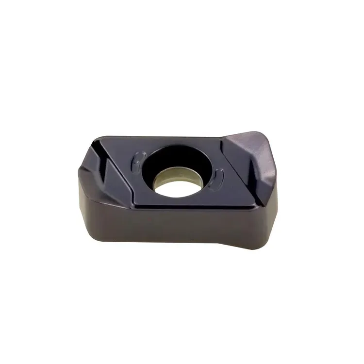
Compact Insert Platform for Productive High-Feed Milling
LNMU0303ZER combines double-sided economy with a shallow axial depth of cut and high feed per tooth. It is intended for compatible high-feed cutter bodies rather than conventional deep shoulder milling.
Four Usable Edges
Two cutting edges per side help reduce the cost per indexed edge.
Compact Size-03 Platform
Supports small- and medium-diameter high-feed cutter systems.
Shallow Axial Cutting
Common ZER systems use an APMX reference of about 1.0 mm; verify the complete cutter and insert combination.
High-Feed Geometry
A small entering angle produces thinner chips and directs more of the cutting load toward the spindle axis.
What Is an LNMU High-Feed Insert?
LNMU0303ZER is a double-sided rectangular high-feed milling insert used in compatible small entering-angle cutter bodies.
The complete designation identifies the insert family, size and high-feed geometry. Similar-looking rectangular inserts are not automatically interchangeable because width, thickness, hole design, edge preparation and cutter-pocket seating can differ.
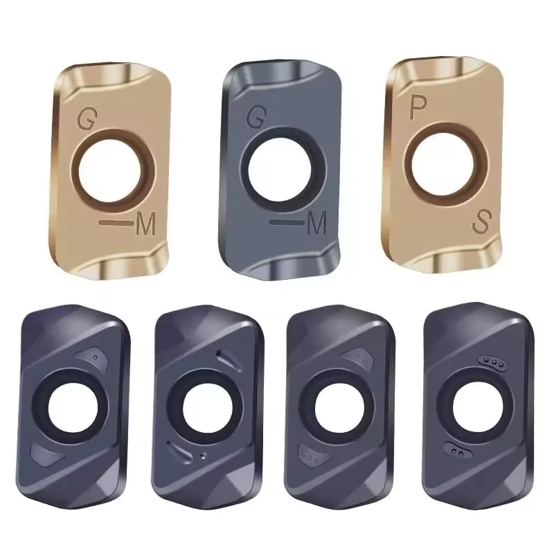
LNMU0303ZER Insert Specifications
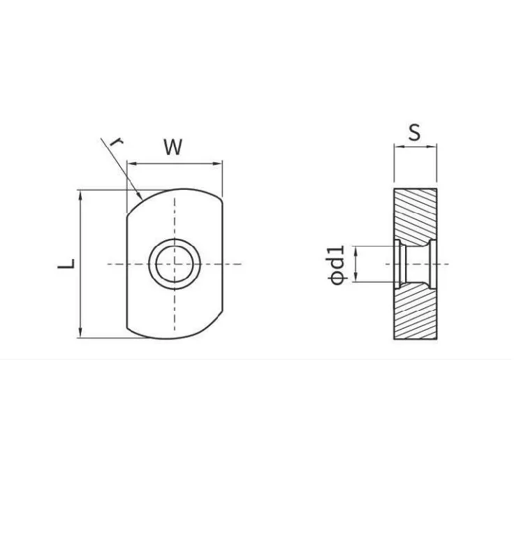
The ordering dimensions below follow the supplied insert catalogue. Because some manufacturers use different dimension symbols and reference surfaces, always compare the technical drawing—not only the family code—when replacing another brand.
| Base Designation | L (mm) | W (mm) | T (mm) | D (mm) | RE (mm) | APMX Reference | Cutting Edges | Compatible Platform |
|---|---|---|---|---|---|---|---|---|
| LNMU0303ZER | 11.4 | 6.0 | 3.75 | 2.85 | 1.2 | 1.0 mm* | 4 | EXN03R end mills / face mills |
LNMU0303ZER-MJ, -ML and -MS Geometry Suffixes
SERP results frequently show LNMU0303ZER with MJ, ML or MS suffixes. These suffixes are manufacturer-specific chipbreaker references, not universal ISO codes, so use the full insert designation when requesting a replacement.
General-Purpose Geometry
Commonly positioned for general high-feed milling with a balance of cutting-edge strength and productivity.
Low-Cutting-Force Geometry
Commonly uses a sharper edge for reduced cutting force, long overhangs and less-rigid setups.
Stainless-Steel Direction
Marketed by some manufacturers for stainless steel and heat-resistant materials with an application-specific edge form.
LNMU Grade Selection by Workpiece Material
Use these grade directions as a selection guide, then confirm current availability for the complete LNMU0303ZER geometry and coating combination.
Tough PVD grade direction for common steel, cast iron and interrupted or less-stable high-feed milling.
PVD grade direction for steel and stainless steel where cutting stability and edge reliability are required.
Wear-resistant direction for stable steel and cast-iron milling, including selected dry-cutting conditions.
General-purpose PVD grade direction across steel, stainless steel and cast iron.
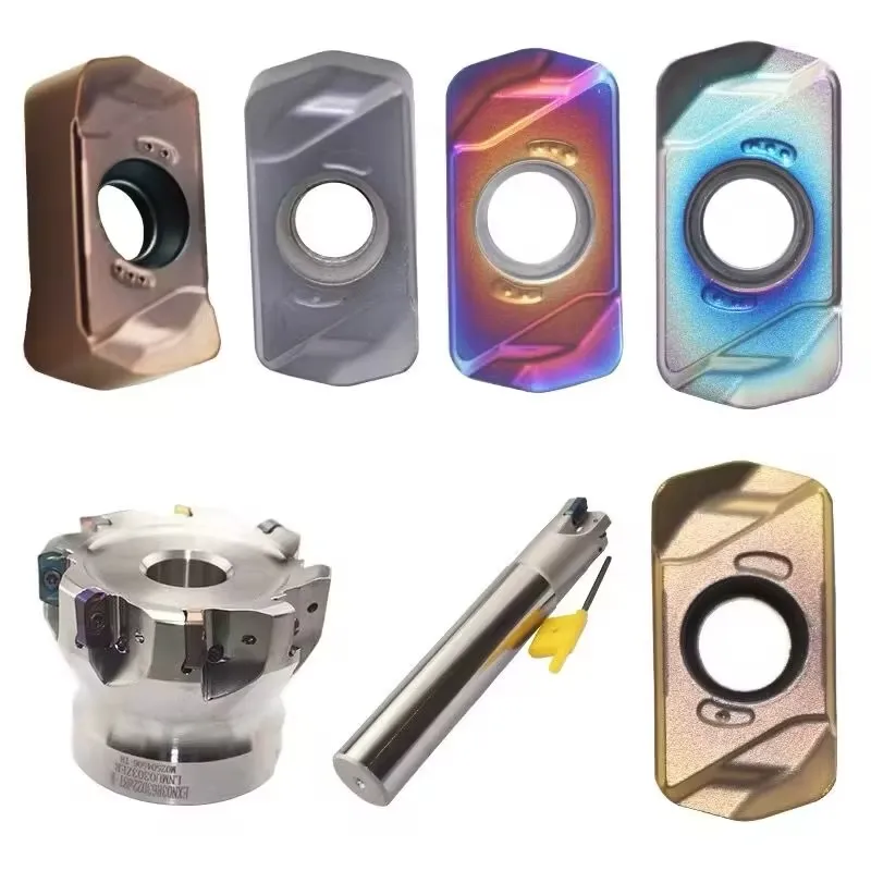
Match LNMU0303ZER Inserts to EXN03R Cutters
EXN03R is the main cutter keyword associated with LNMU0303ZER in current search results and in the supplied cutter catalogues. Match the complete cutter code, diameter, shank or bore, number of teeth and body length.
Double-Sided Design with Four Usable Cutting Edges
LNMU0303ZER provides two cutting edges on each side. Correct indexing and stable pocket seating allow four usable edges before the insert is replaced.
LNMU0303ZER Milling Applications
Actual ramping angle, helical capability, feed and depth depend on the complete cutter body, geometry, grade, machine rigidity and workpiece setup.
High-Feed Face Milling
Rapid removal of shallow stock using high feed per tooth and a small axial depth of cut.
High-feed milling toolsPocket and Mould Roughing
Roughing cavities, mould pockets and residual stock where chip evacuation is controlled.
Ramping and Helical Entry
Oblique or circular entry only where the complete EXN03R cutter model supports the programmed angle.
Long-Overhang Milling
Small entering-angle geometry can reduce radial load and improve stability in selected long-reach setups.
How to Choose an LNMU0303ZER Insert
Frequently Asked Questions
What is LNMU0303ZER used for?
How many cutting edges does an LNMU0303ZER insert have?
What are the catalogue dimensions of LNMU0303ZER?
Which cutter uses LNMU0303ZER inserts?
Are LNMU0303ZER-MJ, -ML and -MS interchangeable?
Request LNMU0303ZER Pricing and EXN03R Compatibility Review
Provide the complete insert code, geometry suffix, grade and EXN03R cutter details so the correct replacement and application direction can be checked.