Gewindewirbel-Einsätze
Maßgeschneiderte Hartmetall-Wendeschneidplatten und Fräskörperlösungen für Schneckenwellen, Knochenschrauben, Leitspindeln, Rotoren und andere lange oder komplexe Außengewinde.
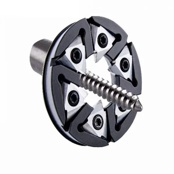
Mehr als nur ein Profileinsatz
Ein stabiler Wirbelbearbeitungsprozess hängt vom gesamten Werkzeugsystem ab. ONMY betrachtet das Wendeplattenprofil, die Aufnahme im Fräskörper, die Spiralneigung, das Werkstückmaterial und die geforderte Gewindequalität als ein Gesamtkonzept.
- Vollprofilgeometrie, abgeleitet aus Steigung, Teilung, Startpunkten, Durchmessern, Flankenwinkeln und Radien
- Einsetzplattform und Passflächen, die auf den vorhandenen Fräskörper oder eine neue Werkzeugkonstruktion abgestimmt sind
- Auf das Material und die Verschleißart abgestimmtes Hartmetallsubstrat, PVD-Beschichtung und Schneidkantenpräparation
- Ersatz-Einsätze können anhand von Zeichnungen, Mustern und Angaben zur Tasche bewertet werden

Geometrie einfügen
Maßgeschneiderter Vollprofil-Schleifvorgang mit anwendungsspezifischem Spanwinkel und Freiraum.
Schneidkörper
Es werden die Tasche, der Schnittdurchmesser, die Anzahl der Schneideinsätze und die Maschinenschnittstelle überprüft.
Prozessunterstützung
Die Zeichnung und die aktuellen Bearbeitungsprobleme dienen als Grundlage für die Werkzeugempfehlung.
Wählen Sie nach dem von Ihnen hergestellten Bauteil aus
Auf der allgemeinen Übersichtsseite wird das Bearbeitungssystem vorgestellt. Jede Anwendungsseite befasst sich anschließend mit der Gewindegeometrie, dem Werkstückmaterial und den für die jeweilige Bauteilfamilie erforderlichen Informationen.

Schneckenwellen-Wirbeleinsätze
Maßgefertigte Einsätze für Schneckenwellen, Schneckenschrauben, Lenkschnecken sowie ein- oder mehrgängige Getriebeprofile.
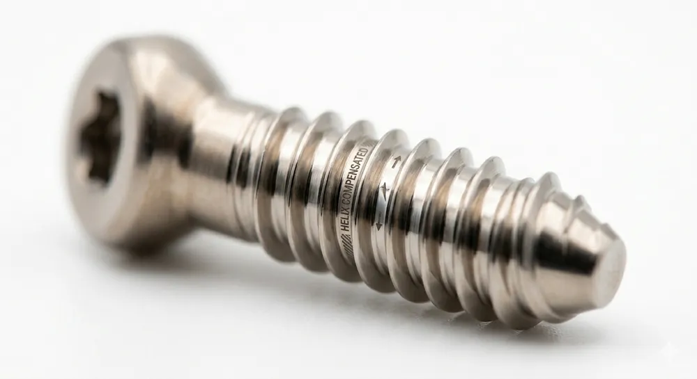
Wirbel-Einsätze für Knochenschrauben
HA-, HB- und Sonderprofil-Einsätze für Knochenschrauben aus Titanlegierungen und Edelstahl, mit passenden D12-Fräskörperoptionen.
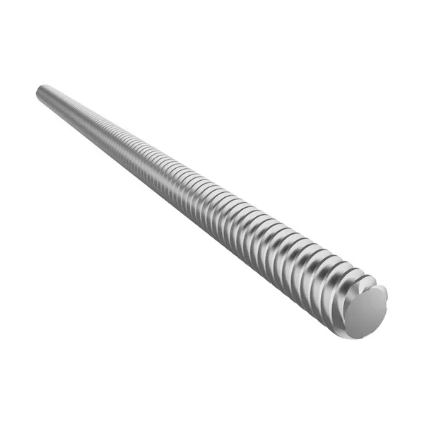
Leitspindel und Rotoreinsätze
Zeichnungsbasierte Wirbeleinsätze für lange Leitspindeln, Vorschubspindeln, Rotoren, Mikrospindeln und Sonderprofile.
Einsatz, Schneidkörper und Maschinenschnittstelle
Dasselbe Gewindeprofil kann sich unterschiedlich verhalten, wenn sich der Fräserdurchmesser, die Anzahl der Schneideinsätze, die Spiralneigung oder die Taschenposition ändern. Diese Details werden überprüft, bevor das Schneideinsatzprofil endgültig festgelegt wird.
Wirbel-Einsatz
Profilgeometrie, Kantenvorbereitung, Hartmetallsorte, Beschichtung und nutzbare Schneidkanten.
Schneidkörper oder Ring
Schnittdurchmesser, Anzahl der Taschen, Schneideinsatzsitz, Rundlauftoleranz und Kühlmittelzufuhr.
Schnittstelle der Wirbelvorrichtung
Maschinenmodell, Anbaugerätemodell, Anschlussmaße und verfügbare Einstellung des Spiralwinkels.
Werkstück und Qualitätsziel
Werkstoff, Gewindetoleranz, Oberflächengüte, Gratkontrolle, angestrebte Standzeit und Produktionsvolumen.
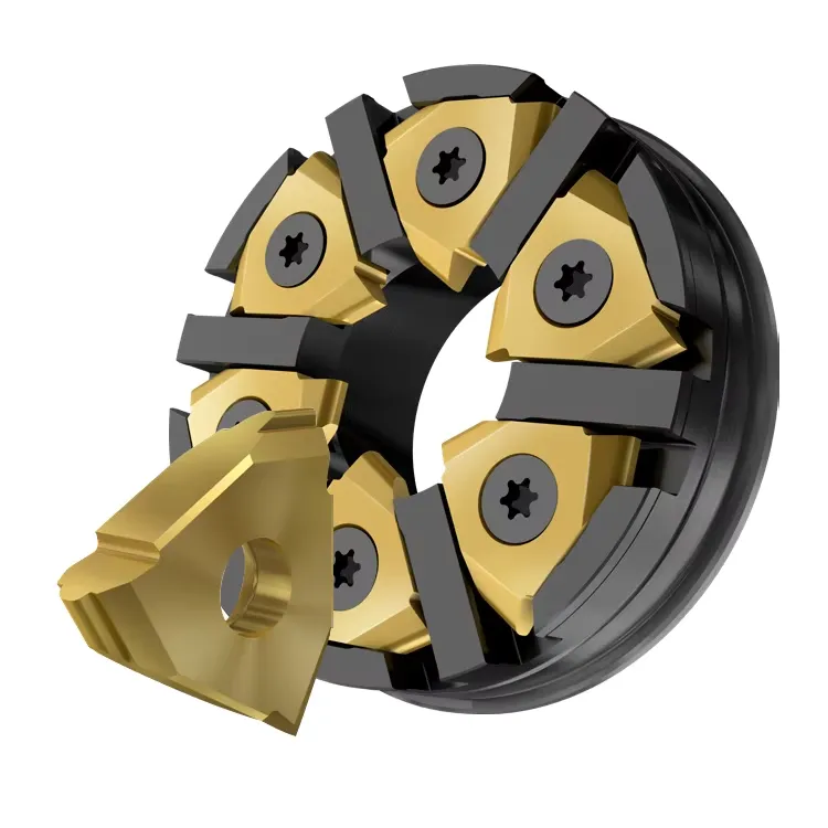
Warum wird das Gewindewirbeln eingesetzt?
Der Schneidkörper dreht sich mit hoher Drehzahl, während sich das Werkstück mit einer geringeren Drehzahl dreht und axial vorgeschoben wird. Mehrere Schneideinsätze teilen sich den Schnitt und bilden das Gewindeprofil nahe am Auflagebereich des Werkstücks.
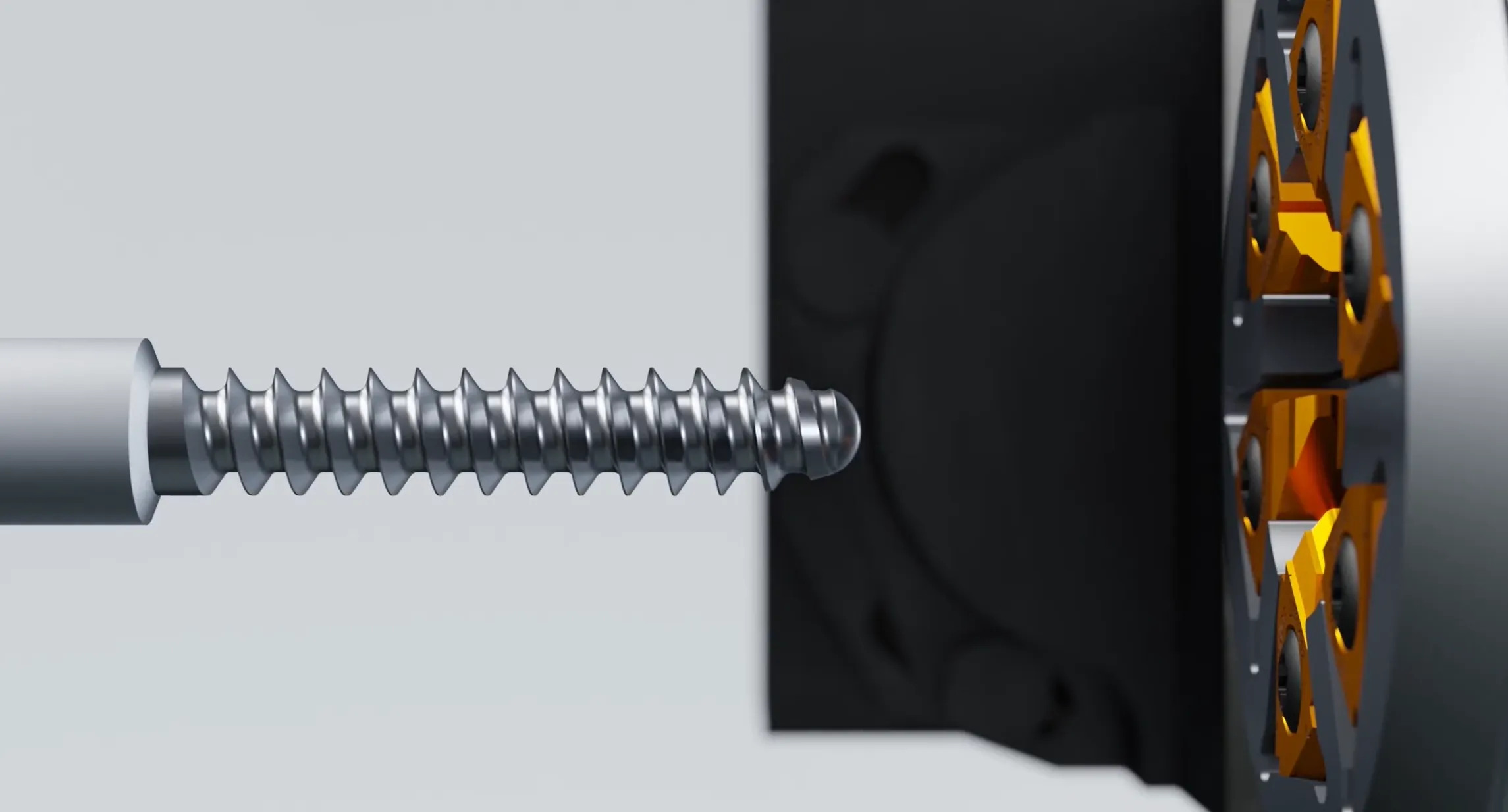
Helix-Beziehung festlegen
Die Wirbelvorrichtung wird auf die Gewindesteigung, den Werkstückdurchmesser und die Maschineneinstellung abgestimmt.
Den Schneidkörper drehen
Mehrere Einsätze führen am Werkstück vorbei und verteilen die Schnittkraft gleichmäßig über den Ring.
Werkstück und Vorschub synchronisieren
Durch die Drehung des Werkstücks und den axialen Vorschub werden die erforderlichen Steigung, Steigungsmaß und Anzahl der Ansätze erzielt.
Das fertige Profil formen
Die Geometrie des Einsatzes erzeugt die vorgegebenen Flanken-, Fuß-, Scheitel- und Übergangsradien.
Auf der Grundlage vollständiger Anwendungsdaten entwickelt
Die Steigung allein reicht nicht aus, um einen Wirbel-Einsatz zu definieren. Das fertige Profil, die Geometrie des Fräskörpers und die Maschineneinstellung müssen gemeinsam betrachtet werden.
Gewinde- und Maschinendaten
Geben Sie die derzeit verfügbaren Informationen an. Fehlende Angaben können im Rahmen der technischen Prüfung ergänzt werden.
Materialien, Kanten und Beschichtungen
Die Auswahl der Beschichtung erfolgt unter Berücksichtigung des Hartmetallsubstrats, der Schneidkantenschärfe, der Werkstoffsorte, des Kühlmittels und der festgestellten Verschleißart.
Gewindewirbeln oder Einpunktdrehen?
Beide Verfahren haben ihre berechtigten Anwendungsbereiche. Die Entscheidung hängt von der Teillänge, der Profiltiefe, der Werkstückauflage, dem Produktionsvolumen und der verfügbaren Maschinenkonfiguration ab.
| Anwendungsfaktor | Gewindewirbeln | Einpunkt-Gewindedrehen |
|---|---|---|
| Lange oder schlanke Werkstücke | Kann dicht an der Führungsbuchse oder dem abgestützten Bereich entlang schneiden, was dazu beiträgt, die Durchbiegung zu begrenzen. | Geeignet, wenn das Werkstück ausreichend steif ist und die radialen Schnittkräfte überschaubar sind. |
| Tiefe oder komplexe Profile | Maßgefertigte Vollprofil-Einsätze ermöglichen die effiziente Formgebung komplexer Geometrien. | Möglicherweise sind mehrere Durchgänge und eine sorgfältige Steuerung der Zuführstrategie erforderlich. |
| Threads mit mehreren Startpunkten | Gut geeignet, wenn die Maschinensynchronisation und die Konstruktion der Einsätze korrekt aufeinander abgestimmt sind. | Eignet sich für die Kleinserienfertigung oder flexible Produktion mit zusätzlichen Programmier- und Durchläufen. |
| Prototyp oder Kleinserie | Praktisch, wenn bereits ein geeigneter Schneidkörper und eine passende Schneideinsatzplattform vorhanden sind. | Oftmals die einfachere Einstiegsmöglichkeit, wenn keine speziellen Wirbelwerkzeuge zur Verfügung stehen. |
Was sollten Sie für eine Werkzeugprüfung einreichen?
Am besten dient die vollständige Gewinde- oder Teilzeichnung als Ausgangspunkt. Auch eine aktuelle Zeichnung des Schneideinsatzes oder des Fräskörpers sowie ein scharfes Foto der Aufnahme können dabei helfen, die Kompatibilität zu überprüfen.
Fragen zu Gewindewirbel-Einsätzen
Praktische Antworten für Einkäufer, die einen maßgefertigten Einsatz, ein Ersatzwerkzeug oder eine neue Wirbelbearbeitungsanwendung in Betracht ziehen.
Kann ONMY Einsätze anhand einer fertigen Gewindeskizze herstellen?
Ja. Die vollständige Zeichnung wird zusammen mit der Aufnahme im Fräskörper, der Maschineneinstellung, dem Werkstückmaterial und der Gewinderichtung geprüft. Die Steigung allein reicht für eine endgültige Gestaltung der Schneideinlage nicht aus.
Kann man einen vorhandenen Wirbeleinsatz austauschen?
Ein Ersatzeinsatz lässt sich anhand der Originalzeichnung, eines brauchbaren Musters, der Abmessungen der Einsatzaufnahme und des gewünschten fertigen Gewindeprofils bewerten. Die Bereitstellung aller vier Angaben bietet die zuverlässigste Ausgangsgrundlage.
Unterstützen Sie Single-Start- und Multi-Start-Threads?
Ja. Die Anzahl der Starts, die Steigung, der Versatz, die Drehrichtung und die Maschinensynchronisation müssen bei der Antragsprüfung bestätigt werden.
Welche Werkstoffe lassen sich bearbeiten?
Zu den typischen Anwendungsbereichen zählen Titanlegierungen, rostfreie Stähle und legierte Stähle. Die Wahl des geeigneten Hartmetalls, der Beschichtung und der Schneidkantenvorbereitung hängt von der Werkstoffsorte und den Schnittbedingungen ab.
Liefern Sie neben Schneideinsätzen auch Schneidkörper?
Die Lieferung oder Entwicklung von Fräskörpern kann auf der Grundlage des Schnittdurchmessers, der Anzahl der Schneideinsätze, der Taschenplattform und der Schnittstellenzeichnung der Wirbelvorrichtung besprochen werden.
Welche Angaben werden für ein Angebot benötigt?
Bitte senden Sie uns die Teilzeichnung, das Gewindeprofil, das Material, das Maschinenmodell, die Angaben zum Wirbelkopf, die derzeitige Werkzeugausstattung sowie das Qualitäts- oder Standzeitproblem, das Sie beheben möchten.
Besprechen Sie Ihre Anwendung im Bereich „Thread Whirling“
Senden Sie Ihre verfügbaren technischen Informationen direkt von dieser Seite aus. ONMY prüft das Profil, die Werkzeugaufnahme, das Material und das aktuelle Bearbeitungsproblem.
- Teilzeichnung oder vergrößerte Zeichnung des Gewindeprofils
- Steigung oder Vorsprung, Startpunkte, Links- oder Rechtsausrichtung sowie Toleranzen
- Werkstoff, Härte und Anforderungen an die Oberflächengüte des Werkstücks
- Details zu Maschine, Drehkopf, Schneidkörper und Einsatztasche
- Aktuelles Einsatzmuster, angestrebte Standzeit oder Bearbeitungsproblem
Senden Sie uns Ihre Zeichnung und die Angaben zu Ihrem Antrag
Füllen Sie die derzeit verfügbaren Felder aus. Fehlende technische Angaben können nach der ersten Prüfung ergänzt werden.
Fügen Sie bei Ersatzeinsätzen nach Möglichkeit ein klares Foto des Einsatzes, Angaben zur Tasche sowie die fertige Gewindeskizze bei.