Dişli Dönme Uçları
Sonsuz vidalar, kemik vidaları, kılavuz vidalar, rotorlar ve diğer uzun veya karmaşık dış dişler için özel profilli karbür kesici uçlar ve kesici gövde çözümleri.
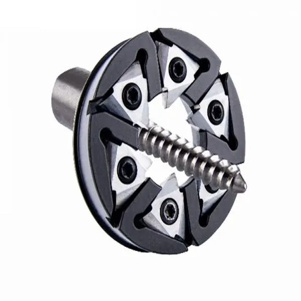
Bir profil ekinden daha fazlası
Kararlı bir tornalama işlemi, tüm takım sistemine bağlıdır. ONMY, kesici uç profili, kesici gövdesi yuvası, sarmal ayarı, iş parçası malzemesi ve istenen diş kalitesini tek bir uygulama kapsamında değerlendirir.
- Adım, adım aralığı, başlangıç noktaları, çaplar, yan yüzey açıları ve yarıçaplardan geliştirilen tam profil geometrisi
- Mevcut kesici gövdesine veya yeni bir takım tasarımına uygun platform ve konumlandırma yüzeylerinin eklenmesi
- Malzeme ve aşınma şekline göre seçilen karbür alt tabaka, PVD kaplama ve kesici kenar hazırlığı
- Yedek ek parçalar, çizimler, numuneler ve yuva bilgilerine göre değerlendirilebilir

Geometri ekleme
Uygulamaya özel kesme açısı ve boşluk ile özel tam profil taşlama.
Kesici gövdesi
Cep, kesme çapı, kesici uç sayısı ve makine arayüzü incelenir.
Süreç desteği
Çizim ve mevcut işleme sorunları, takım seçimi önerisinin belirlenmesinde yol gösterici olur.
Ürettiğiniz parçaya göre seçim yapın
Genel tanıtım sayfası, kalıplama sistemini tanıtmaktadır. Ardından her bir uygulama sayfası, ilgili parça grubu için gerekli olan vida geometrisi, iş parçası malzemesi ve bilgilere odaklanmaktadır.

Sonsuz Mil Dönen Uçlar
Sonsuz mil, sonsuz vida, direksiyon sonsuz dişlisi ve tek sarmalı veya çok sarmalı şanzıman profilleri için özel ek parçalar.
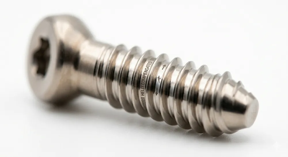
Kemik Vidası Dönme Uçları
Titanyum alaşımlı ve paslanmaz çelik kemik vidaları için HA, HB ve özel profilli uçlar; bunlara uygun D12 kesici gövde seçenekleri.
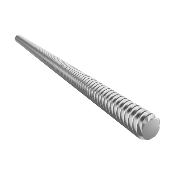
Kılavuz Vida ve Rotor Ek Parçaları
Uzun kılavuz vidalar, besleme vidaları, rotorlar, mikro vidalar ve standart dışı profiller için çizim temelli döner uçlar.
Ek parça, kesici gövdesi ve makine arayüzü
Kesici çapı, kesici uç sayısı, sarmal ayarı veya cep konumu değiştiğinde, aynı diş profili farklı davranışlar sergileyebilir. Bu ayrıntılar, kesici uç profili kesinleştirilmeden önce teyit edilir.
Dönen uç
Profil geometrisi, kenar hazırlığı, karbür kalitesi, kaplama ve kullanılabilir kesme kenarları.
Kesici gövdesi veya halkası
Kesme çapı, cep sayısı, kesici uç yuvası, salgı toleransı ve soğutma sıvısı erişimi.
Dönme ünitesi arayüzü
Makine modeli, ataşman modeli, bağlantı boyutları ve mevcut vida açısı ayarı.
İş parçası ve kalite hedefi
Malzeme, diş toleransı, yüzey kalitesi, çapak kontrolü, takım ömrü hedefi ve üretim hacmi.
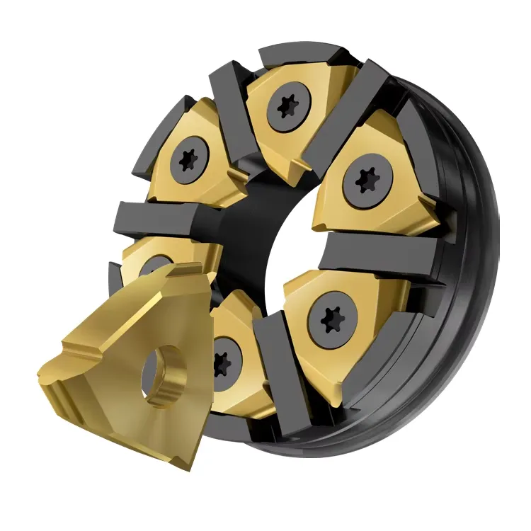
Neden vida sarmalama yöntemi kullanılır?
Kesici gövdesi yüksek hızda dönerken, iş parçası daha düşük bir hızda döner ve eksenel yönde ilerler. Birden fazla kesici uç, kesme işlemini paylaşır ve iş parçasının desteklenen bölgesine yakın bir noktada diş profilini oluşturur.
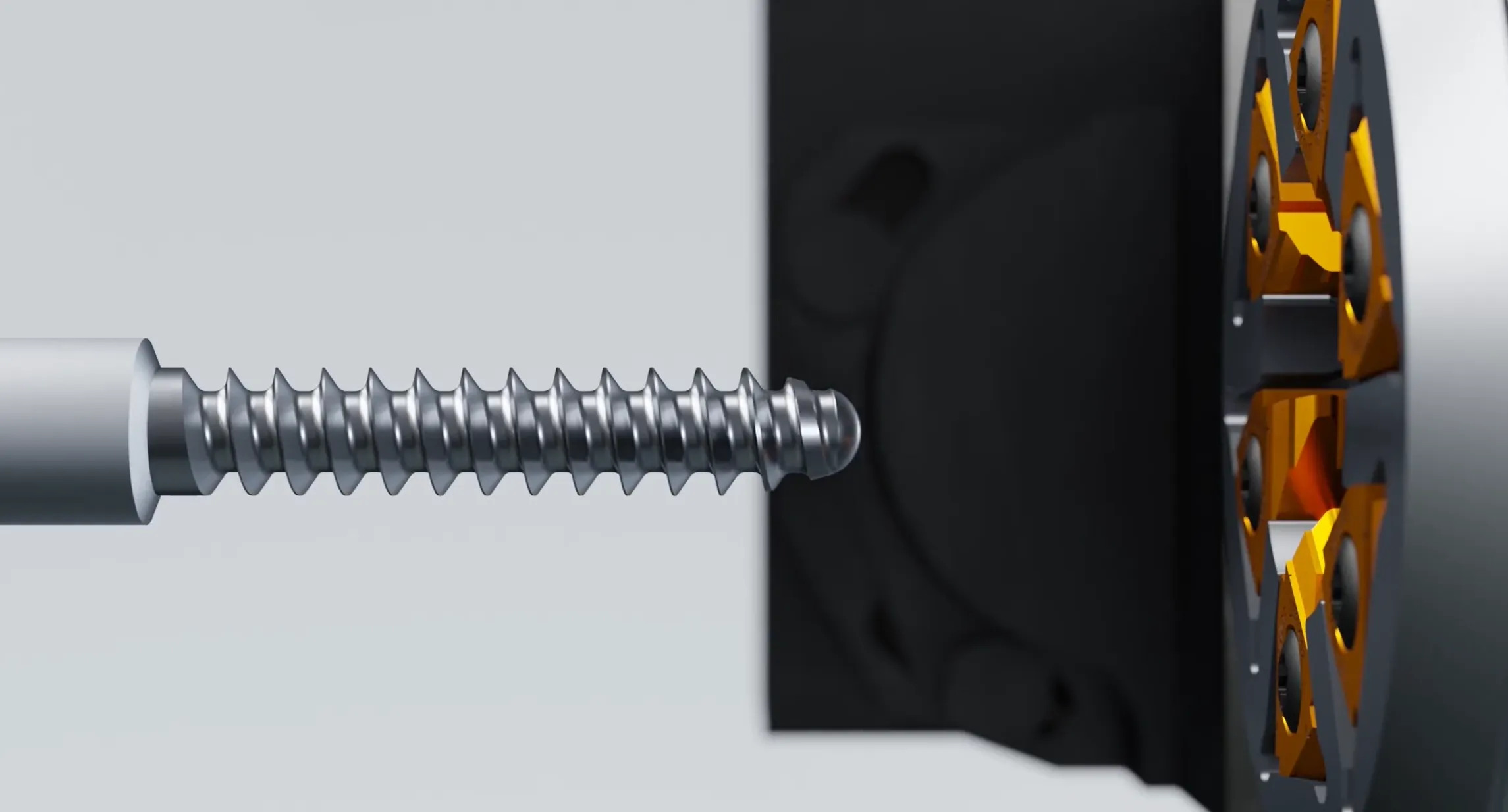
Heliks ilişkisini ayarla
Dönme ünitesi, diş aralığı, iş parçası çapı ve makine ayarlarına göre hizalanır.
Kesici gövdesini döndürün
Birden fazla kesici uç, iş parçasının yanından geçer ve kesme yükünü halka boyunca dağıtır.
İş parçasını ve ilerlemeyi senkronize et
İş parçasının dönüşü ve eksenel ilerlemesi, gerekli adım, adım aralığı ve başlangıç sayısını sağlar.
Bitmiş profili şekillendirin
Ek parça geometrisi, belirtilen yan yüzey, kök, tepe ve geçiş yarıçaplarını oluşturur.
Uygulama verilerinin tamamı temel alınarak tasarlanmıştır
Bir döner kesici ucu, yalnızca eğim açısı ile tanımlanamaz. Bitmiş profil, kesici gövdesi geometrisi ve makine ayarları birlikte değerlendirilmelidir.
İplik ve makine verileri
Şu anda elinizde bulunan bilgileri verin. Eksik detaylar teknik inceleme sırasında teyit edilebilir.
Malzemeler, kenarlar ve kaplamalar
Kaplama seçimi, karbür alt tabaka, kenar keskinliği, iş parçası kalitesi, soğutma sıvısı ve gözlemlenen aşınma şekli dikkate alınarak yapılır.
Döner tornalama mı, yoksa tek noktalı tornalama mı?
Her iki işlem de uygun uygulama alanlarına sahiptir. Karar, parça uzunluğuna, profil derinliğine, iş parçası desteğine, üretim hacmine ve mevcut makine kurulumuna bağlıdır.
| Uygulama faktörü | İplik dönüyor | Tek noktalı diş açma |
|---|---|---|
| Uzun veya ince iş parçaları | Kılavuz burcuna veya desteklenen alana yakın kesim yapabilir ve bu sayede sapmanın kontrol edilmesine yardımcı olur. | Parça yeterince rijit olduğunda ve radyal kesme kuvvetleri kontrol edilebilir olduğunda uygundur. |
| Derin veya karmaşık profiller | Özel tam profil kalıplar, karmaşık geometrik şekilleri verimli bir şekilde oluşturabilir. | Birden fazla geçiş ve besleme stratejisinin dikkatli bir şekilde kontrol edilmesi gerekebilir. |
| Çoklu başlangıçlı iş parçacıkları | Makine senkronizasyonu ile insert tasarımı doğru bir şekilde uyumlu olduğunda son derece uygundur. | Ek programlama ve geçişler sayesinde, düşük hacimli veya esnek üretim için kullanışlıdır. |
| Prototip veya küçük seri üretim | Uygun bir kesici gövdesi ve kesici uç platformu halihazırda mevcut olduğunda kullanışlıdır. | Özel bir döner işleme aletinin bulunmadığı durumlarda genellikle tercih edilen daha basit başlangıç seçeneğidir. |
Kalıp incelemesi için ne göndermelisiniz?
En yararlı başlangıç noktası, dişli veya parça çiziminin tamamıdır. Güncel bir kesici uç, kesici gövdesi çizimi veya net bir cep fotoğrafı da uyumluluğu doğrulamaya yardımcı olabilir.
Tornalama uçlarıyla ilgili sorular
Özel bir ek parça, yedek alet veya yeni bir whirling uygulamasını değerlendiren alıcılar için pratik çözümler.
ONMY, hazır bir vida çiziminden ek parçalar üretebilir mi?
Evet. Tam çizim, kesici gövdesi yuvası, makine ayarları, iş parçası malzemesi ve diş yönü ile birlikte incelenir. Son kesici uç tasarımı için sadece adım mesafesi yeterli değildir.
Mevcut bir döner uç parçası değiştirilebilir mi?
Yedek uç, orijinal çizim, kullanılabilir bir numune, uç yuvasının boyutları ve istenen bitmiş diş profili temel alınarak değerlendirilebilir. Bu dört unsurun tümünün sağlanması, en güvenilir başlangıç noktasını oluşturur.
Tek başlangıçlı ve çoklu başlangıçlı iş parçacıklarını destekliyor musunuz?
Evet. Başlatma sayısı, eğim, ön mesafe, el yönü ve makine senkronizasyonu, başvuru incelemesi sırasında teyit edilmelidir.
Hangi malzemeler işlenebilir?
Tipik uygulama alanları arasında titanyum alaşımları, paslanmaz çelikler ve alaşımlı çelikler yer alır. Kullanılacak karbür, kaplama ve kenar hazırlığı, malzeme kalitesine ve kesme koşullarına bağlıdır.
Kesici gövdelerinin yanı sıra kesici uçları da tedarik ediyor musunuz?
Kesici gövdesinin temini veya geliştirilmesi, kesme çapı, kesici uç sayısı, cep platformu ve döner ünitenin arayüz çizimi temel alınarak görüşülebilir.
Fiyat teklifi için hangi bilgiler gereklidir?
Parça çizimini, diş profilini, malzemeyi, makine modelini, döner kafa bilgilerini, mevcut takımları ve iyileştirmek istediğiniz kalite veya takım ömrü sorununu bize gönderin.
Konu Döndürme Uygulamanızı Tartışın
Elinizdeki teknik bilgileri doğrudan bu sayfadan gönderin. ONMY, profili, takım arayüzünü, malzemeyi ve mevcut işleme sorununu inceleyecektir.
- Parça çizimi veya büyütülmüş diş profili çizimi
- Eğim veya eğim açısı, başlangıç noktaları, sol veya sağ yön ve toleranslar
- İş parçası malzemesi, sertlik ve yüzey kalitesi gereksinimi
- Makine, döner kafa, kesici gövdesi ve kesici uç yuvası detayları
- Mevcut kesici uç numunesi, takım ömrü hedefi veya işleme sorunu
Çiziminizi ve Başvuru Bilgilerinizi Gönderin
Şu anda mevcut olan alanları doldurun. Eksik teknik detaylar, ilk incelemenin ardından teyit edilebilir.
Yedek ekler için, mümkün olduğunca net bir ek fotoğrafı, cep bilgileri ve bitmiş vida diş çizimini ekleyin.