In the world of precision machining, having the right tools can make all the difference between a good product and a great one. Among these essential tools, the U drill stands out as a versatile and efficient option for creating high-quality holes in various materials. This comprehensive guide will delve into the world of U drills, exploring their features, applications, and best practices for use.
What is a U Drill?
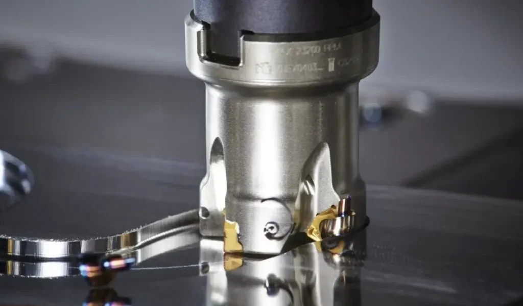
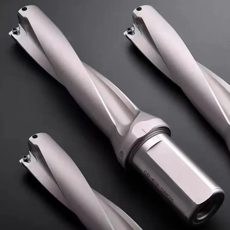
A U drill, also known as a indexable insert drill, is a specialized cutting tool designed for efficient and precise hole-making operations. Unlike traditional twist drills, U drills feature a unique U-shaped flute design that allows for better chip evacuation and improved cutting performance. This innovative design makes U drills particularly suitable for high-speed machining and applications requiring superior hole quality.
Key features of U drills include:
- Replaceable carbide inserts
- Self-centering capabilities
- Excellent chip control
- High cutting speeds and feed rates
- Versatility across various materials
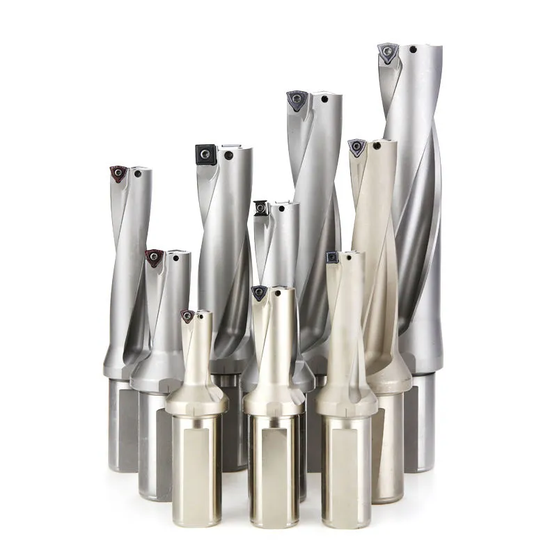
U Drill Size Chart and Standard Sizes
Understanding U drill sizes is crucial for selecting the right tool for your specific application. U drill size charts typically include information on drill diameter, overall length, and insert specifications. Standard U drill sizes range from small diameters of 0.472 inches (12mm) up to larger sizes of 2.559 inches (65mm) or more, depending on the manufacturer.
When consulting a U drill size chart, consider the following factors:
- Hole diameter required
- Material being drilled
- Depth of the hole
- Machine specifications
It’s important to note that U drill sizes may vary slightly between manufacturers, so always refer to the specific U drill size chart provided by your tooling supplier.
Applications of U Drill
U drills find applications across a wide range of industries and materials due to their versatility and efficiency. Some common U drill applications include:
- Automotive: Engine blocks, transmission housings, brake components
- Aerospace: Structural components, landing gear parts
- Oil and Gas: Drill bits, valves, flanges
- General Manufacturing: Machine frames, molds, dies
U drills excel in drilling various materials, including:
- Steel and stainless steel
- Cast iron
- Aluminum and other non-ferrous metals
- Composites
Techniques For Using U Drill On CNC Machine Tools
- U drills require high rigidity of the machine tool and tool-workpiece centration, so they are suitable for use on large power, high rigidity, and high-speed CNC machine tools.
- When using U drills, select inserts with good toughness for the center insert, and sharper inserts for the peripheral inserts.
- For different materials, select inserts with different chip slot shapes. Generally for small feeds, small tolerances, and larger bore-to-diameter ratios, use inserts with smaller cutting forces; whereas for roughing, large tolerances, and smaller bore-to-diameter ratios, use inserts with larger cutting forces.
- Always consider the machine spindle power, U drill clamping stability, coolant pressure, and flow rate during use, and control chip removal to avoid affecting hole surface roughness and dimensional accuracy.
- Ensure the U drill center coincides with and is perpendicular to the workpiece surface during clamping.
- Select suitable cutting parameters according to the workpiece material.
- During trial cutting, do not carelessly reduce feed rates or lower speeds to avoid breaking or damaging the U drill insert or tool.
- When inserts show wear or break during use, analyze the reasons carefully and replace them with more tough or wear-resistant inserts.
- When machining multi-step holes, start with larger holes and then process smaller holes.
- Ensure sufficient coolant pressure to flush chips during U drilling.
- Do not mix up inserts for the center and periphery of U drills, otherwise, the U drill shank may be damaged.
- When drilling with a U drill, workpiece rotation, tool rotation, or simultaneous rotation can be used; but linear feed is commonly used with workpiece rotation.
- Consider the machine’s capability during CNC machining and appropriately adjust cutting parameters, usually lowering speeds and feeds.
U Drill Parameters
Calculation of machining parameters for U-drills (rapid drilling)
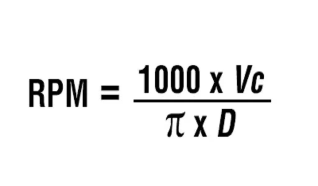
Calculation of drill rotation speed
n = (Vc × 1000) / (3.14 × Dc)
Vc (m/min): Standard value of linear velocity
Dc (mm): Drill diameter
n (rev/min): actual speed of the drill bit
Example: If the linear speed of the insert is 100 m/min and the diameter of the drill bit is 20 mm, the rotational speed of the drill bit is: n = (100 × 1000) / (3.14 × 20) ≈ 1600rev/min
Determination of feed speed
Vf = Fr × n
Vf (mm/min): feed speed of the tool
Fr (mm/rev): feed rate per revolution
n (rev/min): spindle speed
Example: If the spindle speed is 1600rev/min and the feed per revolution is 0.1mm/rev, the feed rate is: Vf = Fr × n = 1600 × 0.1 = 160mm/min
Estimation of hole machining time
Tc = (H / Vf) × 60
Tc (s): time required for machining
H (mm): Depth of hole
Example: Drill a hole with a diameter of 20mm and a depth of 40mm, if the feed rate is 140mm/min, then the machining time is: Tc = (H / Vf) × 60 = (40 / 160) × 60 ≈ 15s
U Drill Cutting Speed
Determining the correct U drill cutting speed is crucial for achieving optimal performance and tool life. U drill cutting speeds are typically higher than those used with conventional drills due to their advanced design and insert technology.
Factors affecting U drill cutting speed include:
- Material hardness and composition
- Drill diameter
- Insert grade and geometry
- Coolant type and delivery method
As a general guideline, U drill cutting speeds for steel can range from 300 to 600 surface feet per minute (SFM), while speeds for aluminum can be significantly higher, often exceeding 1000 SFM. Always refer to the manufacturer’s recommendations and adjust based on your specific application and desired results.
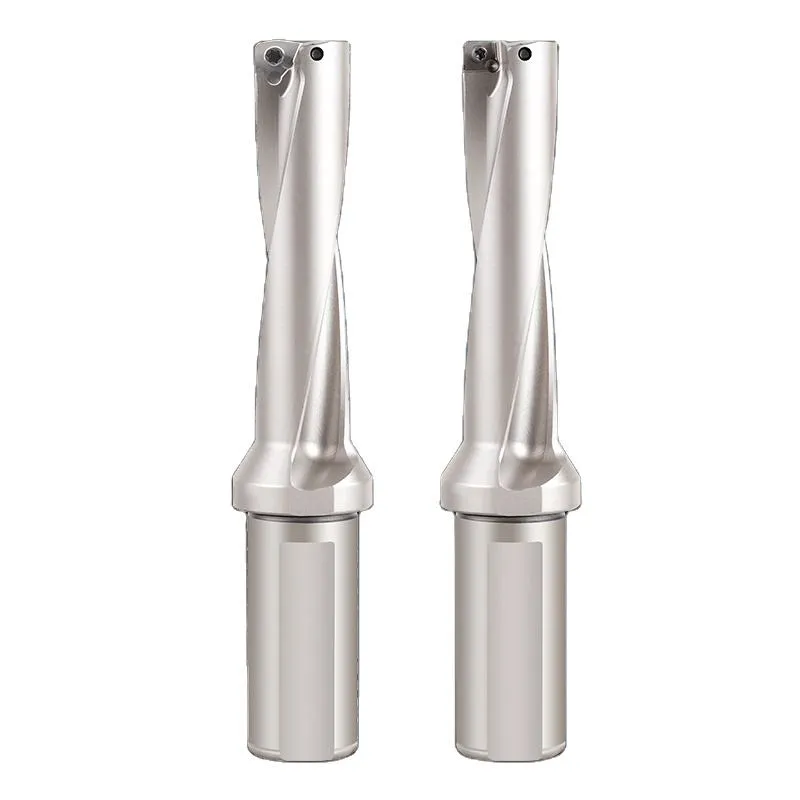
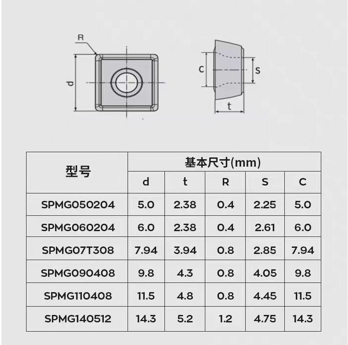
u drill types
U drill types including:spmg insert(spmg 05 insert,spmg 06 insert, spmg 07 insertspmg 09 insert, spmg 11 insert,spmg 14 insert) and wcmx insert(wcmx 03 insert,wcmx 04 insert,wcmx 05 insert,wcmx 06 insert,wcmx 08 insert).

CNC U Drills
The integration of U drills with CNC (Computer Numerical Control) machines has revolutionized the drilling process in modern manufacturing. CNC U drills offer several advantages over manual drilling operations:
- Increased precision and repeatability
- Higher productivity through automated tool changes
- Ability to perform complex drilling patterns and sequences
- Improved process control and monitoring
When using CNC U drills, it’s important to consider factors such as:
- Proper tool holder selection
- Accurate tool length and diameter compensation
- Optimized CNC programming for efficient tool paths
U Drills for VMC (Vertical Machining Centers)
Vertical Machining Centers (VMCs) are versatile machines that can greatly benefit from the use of U drills. When using U drills for VMC applications, consider the following:
- Rigidity of the machine and workpiece holding
- Coolant delivery system capabilities
- Tool change requirements for different hole sizes
- Integration with other machining operations
U drills for VMC applications often feature special adaptations to maximize performance in vertical orientations, such as enhanced coolant channels and optimized insert geometries for gravity-assisted chip evacuation.
Choosing the Right U Drill
Selecting the appropriate U drill for your specific application is crucial for achieving optimal results. Consider the following factors when choosing a U drill:
- Hole diameter and depth requirements
- Material properties
- Machine capabilities
- Production volume
- Surface finish requirements
- Cost considerations (initial investment vs. long-term savings)
Consult with tooling experts and manufacturers to ensure you select the U drill that best meets your needs and maximizes your machining efficiency.
Important Points For Using U Drill
- Pay attention to the correct installation direction – which inserts faces up, down, inside, and outside.
- Center height must be calibrated within a control range of generally 0.1mm depending on diameter. Smaller diameter U drills have higher center height requirements. Improper center height can cause uneven insert wear, oversized holes, and reduced insert life.
- U drills have high coolant requirements – coolant must reach the center and pressure is better with higher pressure. Excess coolant ports can be blocked to ensure pressure.
- Follow manufacturer cutting parameters considerations but also consider different insert brands and machine power. Reference machine load during machining and make suitable adjustments, generally using high speeds and low feeds.
- Inspect and timely replace inserts. Do not reverse inserts.
- Adjust the depth of the cut based on workpiece hardness and insert overhang length. Harder workpieces use greater overhang lengths and smaller depths of cut.
- Do not use excessively worn inserts. Record insert wear vs. machinable workpiece quantities and timely replace inserts.
- Use adequate, correctly pressurized internal coolant. Its primary functions are chip removal and cooling.
- U drills are not suitable for softer materials like purple bronze or soft aluminum.
Maintenance and Care of U Drills
Proper maintenance of U drills is essential for ensuring their longevity and consistent performance. Follow these best practices:
- Regularly inspect inserts for wear and damage
- Clean and lubricate the drill body and inserts
- Store U drills in a clean, dry environment
- Follow manufacturer guidelines for insert indexing and replacement
- Monitor cutting parameters and adjust as needed to prevent premature wear
Troubleshooting common U drill issues:
- Poor hole quality: Check insert condition and cutting parameters
- Excessive vibration: Verify proper tool holder balance and machine rigidity
- Inconsistent hole size: Inspect for insert wear or improper setup
Conclusion
U drills have become an indispensable tool in modern machining operations, offering superior performance and efficiency across a wide range of applications. By understanding U drill size charts, parameters, and best practices, machinists can leverage these versatile tools to achieve exceptional results in their drilling operations.
As technology continues to advance, we can expect to see further innovations in U drill design, materials, and coatings. These developments will likely lead to even higher cutting speeds, improved wear resistance, and expanded applications for U drills in the future.
By mastering the use of U drills and staying informed about the latest advancements in drilling technology, machinists and manufacturers can maintain a competitive edge in the ever-evolving world of precision machining.
What is a U drill and how does it differ from a regular twist drill?
A U drill is an indexable insert drill with a U-shaped flute design, offering better chip evacuation and higher cutting speeds compared to traditional twist drills. It uses replaceable carbide inserts instead of a solid cutting edge.
What materials can be machined with a U drill?
U drills can machine a wide range of materials, including steel, stainless steel, cast iron, aluminum, and other non-ferrous metals. They’re also suitable for some composite materials.
What are the advantages of using a U drill?
Advantages include higher cutting speeds, better hole quality, improved chip evacuation, longer tool life, and the ability to easily replace worn inserts rather than the entire drill.
How do I choose the right U drill size?
Consult a U drill size chart provided by the manufacturer. Consider the required hole diameter, depth, material being drilled, and your machine’s specifications.
What are typical cutting speeds for U drills?
Cutting speeds vary based on material and drill size, but generally range from 300-600 SFM for steel and can exceed 1000 SFM for aluminum. Always refer to manufacturer recommendations.
Can U drills be used in CNC machines?
Yes, U drills are commonly used in CNC machines, including vertical machining centers (VMCs). They integrate well with automated processes.
u drill devir ilerleme?
Devir (Rotation Speed): The rotation speed, or spindle speed, is typically measured in revolutions per minute (RPM). For U drills, the optimal rotation speed depends on several factors:
Material being drilled: Different materials require different cutting speeds.
U drill diameter: Larger diameters generally require lower RPMs.
U drill cutting speed: This is usually provided by the manufacturer in surface feet per minute (SFM) or meters per minute (m/min).
To calculate the appropriate RPM, use this formula: RPM = (SFM x 3.82) / Diameter (in inches)
İlerleme (Feed Rate): The feed rate is the speed at which the drill moves into the workpiece, usually measured in inches per revolution (IPR) or millimeters per revolution (mm/rev).
Factors affecting feed rate include:
Material hardness
Desired hole quality
U drill size
Machine rigidity
U drill manufacturers typically provide recommended feed rates for different materials and drill sizes.