Heavy and semi-heavy machining require chip breakers designed for the task. Wide chip breakers optimize chip control at large depths of cut and high feeds. Cutting edge strength is maximized with a flat, negative land design. Conversely, finishing operations benefit from smaller chip breakers to facilitate chip breaking due to reduced cutting force. In finishing, prioritize cutting edge sharpness with a positive land and small edge honing. CNMM insert excel in roughing applications.
CNMM insert tool holder
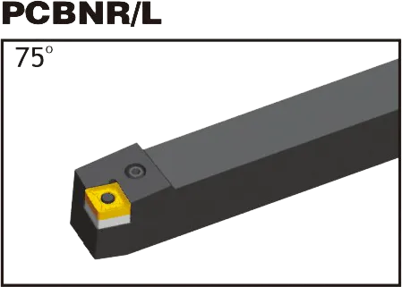
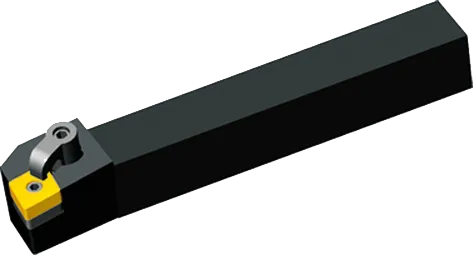
MCLNR/L
CNMM insert Introduction
1. Dimensions
Shape: Rhombic (diamond) with an 80-degree included angle.
Clearance Angle: Negative (typically in the range of -5 to -7 degrees).
Tolerance: Medium (‘M’) is typical, but other tolerances may exist for specialized needs.
Inscribed Circle (IC): Determines the overall insert size (common: 12.7mm, 16mm).
Thickness: Impacts strength and cutting edge count (common: 4.76mm, 6.35mm).
Hugely Important: Chipbreakers shape how chips form and break, ensuring efficient chip flow, tool protection, and workpiece finish.
Manufacturer-Specific: Chipbreaker designations are coded into the CNMM code (the “MM”). Refer to manufacturer catalogs for the specifics.
Match to Operation: Consider:
Workpiece material
Depth of cut (light vs. heavy)
Desired finish
3. Hole Configuration
Central Hole: For secure clamping on toolholders.
Hole-less: Rely on alternative clamping mechanisms.
Toolholder Compatibility: Essential to match the insert’s hole configuration to your toolholder.
4. Coating and Substrate
Coating: Common types include TiN, TiAlN, CVD, and PVD. Each offers different wear resistance, thermal properties, and suitability for various materials.
Substrate: The base carbide material the coating is applied to. Compositions vary, offering toughness vs. wear resistance trade-offs.
Application-Specific: The right grade is crucial for optimal performance and tool life.
CNMM Insert Dimensions (ISO)
ISO Designation
Inscribed Circle (IC)
Thickness
Corner Radius
CNMM 120404
12.7mm (0.5")
4.76mm (0.187")
0.4mm (0.016")
CNMM 120408
12.7mm (0.5")
4.76mm (0.187")
0.8mm (0.031")
CNMM 120412
12.7mm (0.5")
4.76mm (0.187")
1.2mm (0.047")
CNMM 160608
16mm (0.63")
6.35mm (0.25")
0.8mm (0.031")
Example: CNMM 120408
Rhombic (diamond) shape with an 80-degree included angle
Negative clearance angle
Manufacturer-specific details within the “MM” designation
12mm inscribed circle diameter (approx. 0.47″ in inches)
The Science Behind Carbide Inserts: How They're Made and Why They're So Strong
Carbide inserts are some of the most versatile and durable cutting tools available. But how are they made? And what makes them so strong? In this video, we’ll explore the science behind carbide inserts, from the properties of tungsten carbide to the manufacturing process.
Our Production Capability
Find the Perfect CNMM Insert for Your Application – Get Expert Help!