Optimizing Carbide End Mill Cutting Parameters: A Comprehensive Guide
Carbide end mills are essential rotary cutting tools in precision machining, prized for their durability and efficiency in milling operations like slotting, profiling, planar machining, and contouring. Made from tungsten carbide—a composite of tungsten and carbon with cobalt binder—they offer superior hardness (up to 90+ HRA), wear resistance, and heat tolerance compared to high-speed steel (HSS) tools. This allows for higher speeds and feeds, reducing cycle times while maintaining sharp edges longer. Optimizing parameters like spindle speed, feed rate, and depth of cut is critical to balance productivity, surface finish, tool life, and machine safety. Poor settings can lead to excessive wear, breakage, or suboptimal results; ideal ones maximize material removal rate (MRR) and minimize costs. This guide draws on industry best practices to provide formulas, tables, and tips tailored to various materials and scenarios.
Types of Carbide End Mills
Selecting the right type influences parameter choices:
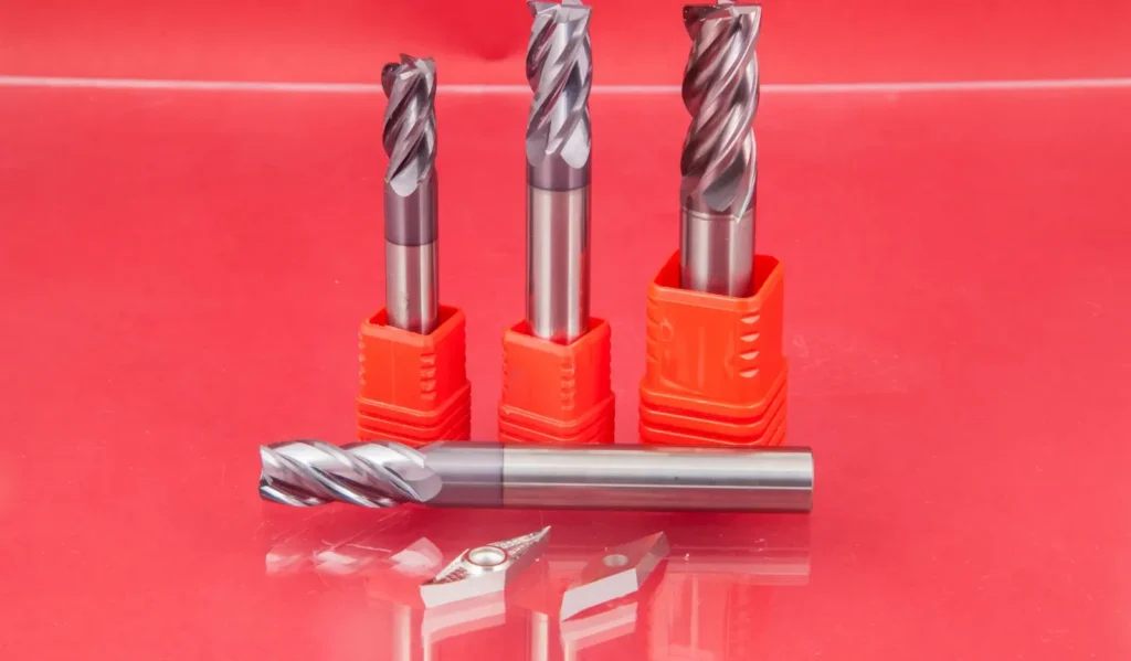
- Flat End Mills: For general flat-bottomed cuts; versatile for roughing and finishing.
- Ball Nose End Mills: For 3D contouring and molds; require adjusted feeds due to curved geometry.
- Corner Radius End Mills: Strengthen edges for heavy roughing; allow higher feeds.
- Roughing End Mills: Coarse teeth for bulk material removal; lower speeds to manage chip load.
- Tapered End Mills: For angled features; parameters scale with effective diameter.
Coatings like TiAlN or AlTiN further optimize for heat and wear, often enabling 20-50% higher speeds on ferrous materials.
Key Cutting Parameters
Master these to achieve optimal performance:
| Parameter | Description | Units (Imperial/Metric) | Typical Range for Carbide End Mills |
|---|---|---|---|
| Spindle Speed (RPM) | Rotations per minute of the tool; controls cutting speed and heat generation. | RPM / RPM | 5,000–10,000 (varies by diameter and material) |
| Feed Rate | Advancement speed into the workpiece; affects chip thickness and MRR. | IPM (inches/min) / mm/min | 10–100 IPM (adjust per tooth) |
| Chip Load (IPT) | Material removed per flute per revolution; key for tool life. | IPT (inches/tooth) / mm/tooth | 0.001–0.010 IPT |
| Axial Depth of Cut (ADOC) | Penetration along tool axis; impacts forces and deflection. | Inches / mm | 0.5–2.5 × tool diameter |
| Radial Depth of Cut (RDOC) | Engagement perpendicular to axis (stepover %); lower for finishing. | % of diameter / mm | 10–50% for roughing; 5–10% for finishing |
| Coolant | Fluid for heat/chip control; flood, mist, or dry based on material. | N/A | Essential for steels/titanium; optional for aluminum |
Calculation Methods
Start with manufacturer data, then refine via formulas. These assume uncoated tools; coatings may increase SFM by 10-30%. Use software like G-Wizard for precision, but manual calcs work for basics.
Spindle Speed (RPM)

- Imperial: RPM = (SFM × 3.82) / Tool Diameter (inches)
- Metric: RPM = (Vc × 1,000) / (π × Tool Diameter in mm) SFM (Surface Feet per Minute) or Vc (m/min) is material-specific (see tables below). Example: For 1/2″ tool in aluminum (SFM=800), RPM = (800 × 3.82) / 0.5 = 6,112.
2. Feed Rate (IPM)
- Imperial: IPM = RPM × IPT × Number of Flutes (T)
- Metric: mm/min = RPM × mm/tooth × T IPT (Chip Load) balances MRR and wear—too low causes rubbing/heat; too high risks breakage. Example: At 6,112 RPM, 0.004 IPT, 4 flutes: IPM = 6,112 × 0.004 × 4 = 98 IPM.
3. Material Removal Rate (MRR)
- MRR = ADOC × RDOC × IPM (cubic inches/min) Maximize by increasing depths/feeds without exceeding machine power (aim for 80% spindle load).

Factors Influencing Optimization
- Workpiece Material: Harder/abrasive materials (e.g., titanium) need lower SFM/higher coolant; soft ones (e.g., aluminum) allow aggressive feeds.
- Tool Geometry: More flutes (3-6) for finishing/high RPM; fewer (2-3) for roughing/chip evacuation. Smaller diameters spin faster but deflect more.
- Machine Rigidity: Stiff setups tolerate deeper cuts; vibrations demand reductions.
- Operation Type: Roughing prioritizes MRR (higher feeds); finishing emphasizes finish (lower RDOC).
- Coolant/Environment: Reduces friction by 30-50%; high-pressure aids titanium chip breaking.
Material-Specific Recommendations
Use these starting points from aggregated guidelines; test and adjust 10-20% based on setup. For a 1/4″ 4-flute end mill.
Non-Ferrous Materials (e.g., Aluminum, Copper)
High speeds, moderate chips; prone to built-up edge without coolant.
| Material | SFM Range | IPT (1/4″ Tool) | RPM Example | Feed (IPM) Example | Tips |
|---|---|---|---|---|---|
| Aluminum (6061) | 800–1,500 | 0.002–0.004 | 9,664–18,120 | 77–145 | High feeds to avoid gumming; MQL preferred. |
| Brass/Copper | 600–1,000 | 0.001–0.002 | 7,248–12,080 | 29–49 | Climb milling; dry if possible. |
| Plastics | 200–600 | 0.003–0.005 | 3,048–9,144 | 37–61 | Sharp tools; low heat to prevent melting. |
Ferrous Materials (e.g., Steel, Stainless)
Moderate speeds; focus on chip control to avoid work-hardening.
| Material | SFM Range | IPT (1/4″ Tool) | RPM Example | Feed (IPM) Example | Tips |
|---|---|---|---|---|---|
| Mild Steel (1018) | 100–300 | 0.001–0.002 | 1,216–3,648 | 5–15 | Flood coolant; 40-60% stepover. |
| Stainless (304) | 100–250 | 0.0005–0.001 | 1,216–3,024 | 2–5 | Lower RDOC (20%); high-pressure coolant. |
| Tool Steel (A2) | 100–250 | 0.001–0.0015 | 1,216–3,024 | 5–7 | Coated tools; monitor for built-up edge. |
High-Temp Alloys & Titanium
Low speeds, light cuts; heat management is key.
| Material | SFM Range | IPT (1/4″ Tool) | RPM Example | Feed (IPM) Example | Tips |
|---|---|---|---|---|---|
| Titanium (6Al-4V) | 50–250 | 0.0005–0.001 | 608–3,024 | 1–5 | Abundant coolant; trochoidal paths for low engagement. |
| Inconel 718 | 40–60 | 0.001–0.0015 | 486–728 | 2–4 | Rigid setup; variable helix tools to reduce chatter. |
RPM Example: (SFM × 3.82) / 0.25. Feed: RPM × IPT × 4 flutes. Scale IPT up 20-50% for larger diameters.
Optimization Strategies
- Start Conservative: Use 70-80% of max recommended SFM/IPT; ramp up while monitoring.
- Monitor Feedback: Listen for chatter (reduce RPM 10%); check chips (short/curly = good; stringy = increase feed).
- Advanced Techniques:
- High-Speed Machining (HSM): 1,500+ SFM with light RDOC (5-10%); boosts MRR 2-3x.
- Trochoidal Milling: Circular paths with 5-15% engagement; ideal for slots, extends life 2x.
- Climb vs. Conventional: Climb for better finish (same-direction feed/tool rotation); conventional for entry cuts.
- Iterate: Adjust in 10% increments; log results for repeatability.
Troubleshooting Common Issues
| Issue | Causes | Solutions |
|---|---|---|
| Tool Breakage | Excessive ADOC/RDOC, high IPT | Reduce depths 20%; check rigidity. |
| Chatter/Vibration | Resonance, deflection | Vary RPM; use shorter tools; add dampers. |
| Poor Finish | Low RPM, high feed | Increase speed; lower IPT; ensure coolant. |
| Chip Buildup | Inadequate evacuation | Boost feed; optimize coolant pressure. |
| Rapid Wear | Heat from dry runs, wrong SFM | Apply fluid; match material recs. |
Best Practices for Tool Life
- Choose the Right Coating: Select a coating (e.g., TiAlN, AlCrN, TiCN) that is specifically optimized for your workpiece material. Coatings increase hardness, heat resistance, and lubricity, which significantly extends tool life, especially in high-speed or dry machining.
- Match Flute Count to Material:
- Lower Flute Count (2-3): Ideal for non-ferrous, gummy, or softer materials (like aluminum) as they offer larger chip valleys for efficient chip evacuation, preventing chip recutting and packing.
- Higher Flute Count (5+): Better for harder, ferrous materials (like steel, stainless steel) as they provide a thicker, more rigid core for strength and stability.
- Minimize Length of Cut (LOC): Use the shortest possible LOC/flute length necessary for the job. A shorter tool is more rigid and less susceptible to deflection, reducing vibration and tool breakage.
- Utilize Variable Helix/Pitch Geometry: Tools with variable helix angles help break up harmonic vibrations (chatter), leading to a smoother cut, better finish, and longer tool life.
- Use Corner Radius (Bullnose) Tools: A bullnose end mill (with a small radius on the corner) is typically more durable than a sharp square end, as the radius distributes cutting forces more evenly and resists chipping.