APMT Carbide Milling Inserts
Compare APMT1135 and APMT1604 carbide milling inserts by dimensions, chipbreaker, corner radius, carbide grade and compatible cutter body. Select inserts for shoulder milling, face milling, side milling, pocketing, ramping and related indexable milling operations.
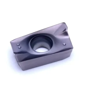

What Is an APMT Milling Insert?
APMT is a positive parallelogram-shaped indexable milling insert commonly used in shoulder, side, pocket and selected face milling cutter systems.
The four letters identify the basic ISO-style form, clearance, tolerance and hole/chip-forming configuration. The following numbers and suffixes identify the size, corner radius, geometry and manufacturer-specific chipbreaker. The four-letter family code alone is not enough to confirm cutter compatibility.
How to Read PDER and PEER in an APMT Designation
PDER and PEER are not chipbreaker names. They describe the wiper code, cutting-edge form and cutting direction. A chipbreaker code appears separately after the hyphen.
APMT1604PDER-M2PD is the wiper code, E is the cutting-edge form, R is the right-hand direction, and M2 is the finishing chipbreaker.
APMT1604PEERPE is the wiper code, followed by edge-form code E and right-hand code R. Because no chipbreaker suffix follows a hyphen, display the chipbreaker as / and treat it as the semi-finishing version shown in the catalogue.
Complete APMT Insert Models and Specifications
All APMT1135 and APMT1604 models shown in the supplied carbide insert catalogue are listed below. Dimensions, chipbreakers and available grades are kept at full-designation level.
How to Use the Tables
Choose the insert platform from the cutter pocket first, then confirm the complete designation, chipbreaker, radius and available grade. A dot shown in the catalogue has been converted into a listed grade in the final column.
APMT1135 Inserts: All Models, Dimensions and Grades
The catalogue contains four APMT1135 base models. All four are listed below with their dimensions, chipbreakers and grade options.
| Catalogue Designation | L (mm) | W (mm) | T/S (mm) | D (mm) | RE (mm) | Chipbreaker | Machining Stage | Grade Options |
|---|---|---|---|---|---|---|---|---|
| APMT1135PDER-ZL | 11.30 | 6.25 | 3.60 | 2.80 | 0.80 | ZL | Semi-finishing | D7320, D9920S |
| APMT1135PEER | 11.30 | 6.25 | 3.60 | 2.80 | 0.80 | / | Semi-finishing | D530, D570, D580, D7320, D8420A, D9920S |
| APMT1135PDER-M2 | 11.30 | 6.20 | 3.50 | 2.80 | 0.80 | M2 | Finishing | D530, D570, D580, D7320, D8420A |
| APMT1135PDER-H2 | 11.30 | 6.20 | 3.50 | 2.80 | 0.80 | H2 | Roughing | D530, D570, D580, D7320, D8420A |
APMT1604 Inserts: All Models, Dimensions and Grades
The catalogue contains nine APMT1604 models, including multiple PDER corner radii and separate ZL, M2 and H2 options.
| Catalogue Designation | L (mm) | W (mm) | T/S (mm) | D (mm) | RE (mm) | Chipbreaker | Machining Stage | Grade Options |
|---|---|---|---|---|---|---|---|---|
| APMT1604PDER-ZL | 17.42 | 9.33 | 5.20 | 4.50 | 0.80 | ZL | Semi-finishing | D7320, D9920S |
| APMT1604PEER | 17.42 | 9.33 | 5.20 | 4.50 | 0.80 | / | Semi-finishing | D530, D570, D580, D7320, D8420A, D9920S |
| APMT160404PDER | 17.25 | 9.33 | 5.20 | 4.50 | 0.80 | / | Semi-finishing | D530, D570, D580 |
| APMT160412PDER | 17.25 | 9.33 | 5.20 | 4.50 | 1.20 | / | Semi-finishing | D530, D570, D580 |
| APMT160416PDER | 17.25 | 9.33 | 5.20 | 4.50 | 1.60 | / | Semi-finishing | D530, D570, D580 |
| APMT160420PDER | 17.25 | 9.33 | 5.20 | 4.50 | 2.00 | / | Semi-finishing | D530, D570, D580 |
| APMT160430PDER | 17.25 | 9.33 | 5.20 | 4.50 | 3.00 | / | Semi-finishing | D530, D570, D580 |
| APMT1604PDER-M2 | 17.25 | 9.25 | 4.76 | 4.40 | 0.80 | M2 | Finishing | D530, D570, D580, D7320, D8420A |
| APMT1604PDER-H2 | 17.25 | 9.25 | 4.76 | 4.40 | 0.80 | H2 | Roughing | D530, D570, D580, D7320, D8420A |
Compatible APMT Insert Cutters and Cutter Bodies
Search performance shows strong interest in APMT cutters and cutter bodies. The table below connects the insert platform to confirmed cutter systems from the supplied cutter catalogues.
Right-Angle Shoulder Cutters
General shoulder, side, pocket and related indexable milling applications.
Larger Shoulder Cutters
Larger cutting-edge platform for roughing and shoulder milling.
75° Face Milling Cutters
Face milling system with APMT platform selected by the complete cutter model.
Compact APMT Cutter System
Small and medium shoulder, side and rough milling direction.
Larger APMT Cutter System
Medium and larger shoulder milling and stock-removal applications.
Deep Shoulder and Side Milling
Extended-edge and corn-type systems for deep shoulders and side milling.
APMT Chipbreaker Options
The chipbreaker is the suffix after the hyphen. PDER and PEER are part of the insert designation structure and must not be used as chipbreaker names.
Semi-Finishing
Use a slash when the complete designation ends with PDER or PEER and no separate suffix follows. In this catalogue, those slash-designated models are used for semi-finishing.
Roughing
H2 is the roughing chipbreaker for stronger-edge and higher-load machining conditions.
Finishing
M2 is the finishing chipbreaker for lighter cutting and improved surface-finish direction.
Semi-Finishing
ZL is the semi-finishing chipbreaker for balancing stock removal, cutting stability and surface quality.
APMT Inserts by Workpiece Material
Choose the complete size, geometry and grade combination. Not every grade is available in every APMT designation.
Steel
Balance edge toughness, wear resistance and chip formation for shoulder, side and pocket milling.
Inserts for steelStainless Steel
Use suitable PVD grades and lower-force geometry to reduce heat, work hardening and built-up edge.
Inserts for stainless steelCast Iron
Wear-resistant grades support stable cast-iron milling and selected dry conditions.
Inserts for cast ironDifficult Materials
Hardened and heat-resistant applications require application review, stable engagement and a verified grade combination.
Difficult-material insertsAPMT Milling Insert Applications
Actual capability depends on the cutter body. APMT is primarily associated with positive shoulder and general indexable milling systems.
Shoulder Milling
Machining a horizontal floor and vertical wall with compatible right-angle cutters.
Face Milling
Selected RAP-75 and related cutter systems for flat-surface roughing and semi-finishing.
Side Milling
Peripheral cutting along walls, steps and external part features.
Pocket Milling
Roughing and profiling inside open pockets with a compatible cutter body.
APMT Corner Radius and Cutting Edges
The size code alone does not fully define corner radius. Use the complete designation and catalogue RE value.
Larger corner radii generally strengthen the edge and may support higher load, but they also increase cutting force and determine the minimum internal corner that can be produced.
How to Choose an APMT Insert
Request APMT Insert Pricing
Send the full insert code, APMT1135 or APMT1604 size, chipbreaker, grade, corner radius, quantity and current cutter-body model. A photo of the cutter pocket or an existing insert can help confirm compatibility.