Climb Milling vs Conventional Milling: A Comprehensive Guide
In the world of machining, choosing the right milling strategy can make or break your project’s success. Two fundamental approaches dominate the field: climb milling and conventional milling. Understanding their differences, applications, and optimal usage scenarios is crucial for achieving superior results in your machining operations.
If you don’t want to read a complicated article, you can also check out the comparison table between the two.
Introduction to Milling Methods
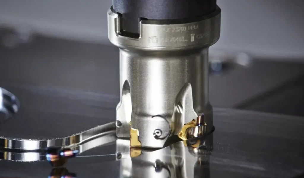
Milling is a machining process that removes material using rotating cutting tools(such as endmills milling,indexable milling). The relationship between the cutter’s rotation direction and the workpiece’s feed direction defines two distinct milling methods. These methods significantly impact surface finish quality, tool life, cutting forces, and overall machining efficiency.
The difference between climb milling and conventional milling lies primarily in the feed direction relative to the cutter’s rotation. This seemingly simple variation creates dramatically different cutting dynamics, each with unique advantages and limitations.
What is Conventional Milling (Up Milling)?
Conventional milling, also known as up milling, occurs when the workpiece feeds against the direction of cutter rotation. In this method, the cutting edge starts with zero chip thickness and gradually increases to maximum thickness as it exits the cut. This creates an upward cutting action that tends to lift the workpiece away from the machine table.

Characteristics of Conventional Milling
The cutting forces in conventional milling create an upward and outward pulling effect on the workpiece. This results in a tendency for the workpiece to vibrate and chatter, particularly during heavy cuts. The initial contact between the cutting edge and workpiece involves a rubbing action before actual cutting begins, which can cause work hardening and increased tool wear.
Surface finish quality in conventional milling is generally rougher compared to climb milling. The cutting action leaves a slightly torn appearance on the machined surface due to the chip formation pattern and the upward lifting forces.
Advantages of Up Cut Milling
What are the advantages of up cut milling? Conventional milling offers several benefits, particularly for older machine tools. It’s more forgiving on machines with backlash in their lead screws, as the cutting forces don’t pull the workpiece into the cutter. This makes it safer for manual machining operations where precise control might be challenging.
Conventional milling is also preferred for interrupted cuts and when machining materials that might grab or pull during cutting. The gradual engagement of the cutting edge provides more controlled entry into the material.
Disadvantages of Up Cut Milling
What are the disadvantages of up cut milling? The primary drawbacks include poor surface finish quality, increased tool wear due to initial rubbing, and higher cutting forces required to maintain the cut. The upward cutting forces can cause workpiece lifting, leading to dimensional inaccuracies and potential safety hazards.
The vibration and chatter associated with conventional milling can also reduce tool life and create unacceptable surface finishes in precision applications.
Understanding Climb Milling (Down Milling)
Climb milling, or down milling, occurs when the workpiece feeds in the same direction as the cutter rotation. The cutting edge immediately engages with maximum chip thickness and reduces to zero as it exits the cut. This creates a downward cutting action that pushes the workpiece firmly against the machine table.

Characteristics of Climb Milling
The cutting forces in climb milling work to clamp the workpiece down against the table, creating more stable cutting conditions. The immediate full engagement of the cutting edge eliminates the rubbing action present in conventional milling, resulting in cleaner cuts and extended tool life.
Surface finish quality is significantly superior in climb milling due to the smooth cutting action and the way chips are formed and evacuated from the cut zone.
Advantages of Climb Milling
Why is climb milling or down milling chosen while machining? The primary reasons include superior surface finish, extended tool life, reduced cutting forces, and better dimensional accuracy. The downward clamping forces create more stable cutting conditions, reducing vibration and chatter.
Climb milling also provides better chip evacuation, as chips are directed away from the finished surface. This prevents re-cutting of chips and reduces the likelihood of surface scratches or damage.
Disadvantages of Climb Milling
The main limitation of climb milling is its requirement for rigid machine tools with minimal backlash. On machines with worn lead screws or excessive play, climb milling can cause the workpiece to be pulled into the cutter, potentially causing tool breakage or workpiece damage.
Comparison Summary: What is Better, Climb or Conventional Milling?
The question of what is better, climb or conventional milling, depends entirely on your specific application requirements and machine capabilities.
Surface Finish Quality
Climb milling consistently produces superior surface finishes due to its smooth cutting action and proper chip formation. Conventional milling typically results in rougher surfaces requiring additional finishing operations.
Tool Life
Climb milling generally extends tool life by eliminating the initial rubbing action and providing more efficient cutting. The immediate full engagement reduces tool wear and heat generation.
Cutting Forces
While both methods generate cutting forces, climb milling’s downward clamping forces are generally more beneficial for workpiece stability. Conventional milling’s upward forces can cause workpiece movement and dimensional variations.
Machine Requirements
Conventional milling is more forgiving on older machines with backlash, while climb milling requires rigid, well-maintained equipment for optimal results.
When to Use Each Method
When to Use Climb Cut
When to use climb cut? Climb milling is preferred for finishing operations, precision machining, and when working with modern CNC machines. It’s ideal for achieving tight tolerances and superior surface finishes.
For climb vs conventional milling aluminum, climb milling is typically preferred due to aluminum’s tendency to weld to cutting tools. The clean cutting action of climb milling reduces built-up edge formation and produces better surface finishes on aluminum components.
When Would Upmilling be Preferred to Downmilling?
When would upmilling be preferred to downmilling? Conventional milling is chosen when working with older machines that have significant backlash, when machining interrupted surfaces, or when operator safety is a primary concern in manual operations.
It’s also preferred for roughing operations where surface finish is less critical, and when machining materials that are prone to grabbing or pulling during cutting.
Conclusion
Understanding the difference between climb milling and conventional milling is essential for optimizing your machining operations. While climb milling generally offers superior results in terms of surface finish and tool life, conventional milling remains valuable for specific applications and machine limitations.
The key to success lies in matching the milling method to your specific requirements: machine capabilities, material properties, surface finish requirements, and operational constraints. By making informed decisions about when and how to apply each method, you can achieve optimal results while maximizing efficiency and tool life.
What is the main difference between climb milling and conventional milling?
The main difference lies in the feed direction relative to cutter rotation. Conventional milling feeds against rotation, while climb milling feeds with rotation.
What is conventional milling best used for?
Conventional milling is best for older machines with backlash, interrupted cuts, and situations where gradual tool engagement is preferred.
Which method is better for aluminum machining?
Climb milling is generally preferred for aluminum due to its clean cutting action and reduced built-up edge formation.
Why choose climb milling over conventional milling?
Climb milling is chosen for superior surface finish, longer tool life, and better dimensional accuracy on rigid machines.
When should I avoid climb milling?
Avoid climb milling on machines with significant backlash or when workpiece rigidity is insufficient to resist pulling forces.
Comparison table
Climb Milling vs Conventional Milling Comparison
| Aspect | Conventional Milling (Up Milling) | Climb Milling (Down Milling) |
|---|---|---|
| PROCESS CHARACTERISTICS | ||
| Feed Direction | Against cutter rotation | With cutter rotation |
| Chip Thickness | Zero to maximum (gradual increase) | Maximum to zero (gradual decrease) |
| Cutting Forces | Upward and outward (lifting workpiece) | Downward (clamping workpiece) |
| Tool Engagement | Gradual engagement with initial rubbing | Immediate full engagement |
| ADVANTAGES | ||
| Surface Finish | Acceptable for roughing operations | Superior finish quality |
| Tool Life | Standard tool life | Extended tool life (20-50% longer) |
| Machine Requirements | Works on machines with backlash | Requires rigid, precise machines |
| Safety | Safer for manual operations | Requires careful setup |
| Vibration Control | More vibration and chatter | Smoother cutting, less vibration |
| DISADVANTAGES | ||
| Surface Quality | Poor surface finish | Excellent surface quality |
| Tool Wear | Higher wear due to rubbing | Minimal initial wear |
| Workpiece Stability | Lifting forces cause instability | Excellent workpiece clamping |
| Machine Compatibility | Compatible with older machines | Not suitable for machines with backlash |
| Risk Factor | Lower risk of workpiece pulling | Risk of workpiece being pulled into cutter |
| OPTIMAL APPLICATIONS | ||
| Operation Type | Roughing operations, interrupted cuts | Finishing operations, precision machining |
| Machine Type | Older mills, manual machines | Modern CNC machines, rigid setups |
| Material Suitability | Hard materials, cast iron | Aluminum, soft steels, precision alloys |
| Tolerance Requirements | Standard tolerances (±0.005″ or looser) | Tight tolerances (±0.001″ to ±0.002″) |
| Production Volume | Low to medium volume | Medium to high volume production |
| WHEN TO CHOOSE | ||
| Best Choice When |
• Machine has backlash • Manual machining required • Interrupted cutting surfaces • Roughing operations • Safety is primary concern |
• Surface finish is critical • Tight tolerances required • Modern CNC equipment available • Aluminum machining • High production volumes |