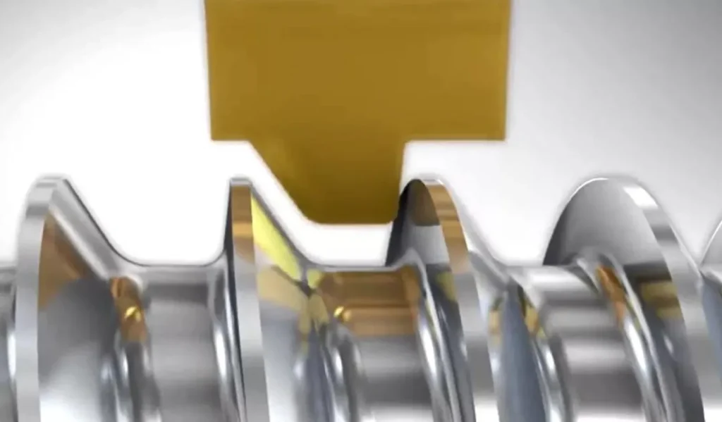
The Ultimate Guide to Shoulder Milling 2025

Shoulder milling is a fundamental machining orking and CNC manufacturing, where a milling cutter simultaneously creates two distinct surfaces on a workpiece: a flat bottom (or face) and a vertical shoulder (a stepped edge), typically at a precise 90-degree angle. This operation combines elements of face milling (for the flat surface) and peripheral (side) milling (for the vertical wall), allowing for efficient material removal in a single pass.
Core Concepts: Face vs. Side vs. Shoulder Milling
To select the correct strategy, one must understand the physics of the cutting action. The primary differentiator is the Lead Angle (Kr) and how it decomposes the cutting force (F) into Axial (Fa) and Radial (Fr) components.
A. The Physics of Forces
The relationship between the cutting forces and the lead angle is governed by:
- Radial Force (Fr): Fr \approx F \times \sin(Kr) (Responsible for deflection/vibration)
- Axial Force (Fa): Fa \approx F \times \cos(Kr) (Presses part into the table)
B. Detailed Comparison Matrix
| Feature | Face Milling (45°) | Shoulder Milling (90°) | Side Milling (0°/90°) |
|---|---|---|---|
| Lead Angle (Kr) | 45° (Standard) | 90° | 0° – 90° (Depends on Helix) |
| Force Decomposition | Balanced: ~50% Radial, ~50% Axial | Dominant Radial (~95%), Minimal Axial | 100% Radial Force |
| Chip Thinning Factor | 0.707 (Significant thinning) | 1.00 (No thinning at >50% Ae) | Depends on Radial Depth (Ae) |
| Tool Engagement | Bottom Face Only | Bottom + Side Wall | Side Wall (Periphery) Only |
| Deflection Risk | Low (Forces directed into spindle) | High (Cantilever effect) | Very High (Tool pushes away) |
| Primary Application | High MRR facing, Flatness | Steps, Pockets, 90° Walls | Profiling, Contouring |
Details you can see about face milling, shoulder milling, profile milling, and fast feed milling article.
C. Deep Dive Analysis
1. Face Milling (45° Lead Angle)
- Mechanism: The 45° angle directs cutting forces upward into the spindle and downward into the part.
- Chip Physics: Due to the angle, the actual chip thickness (h{ex}) is thinner than the programmed feed per tooth (fz).
- Formula: Formula: h{ex} = fz *(sin45°)≈0.7*fz
- Implication: You can run feed rates 1.4x higher than a 90° cutter to achieve the same chip load.
2. Shoulder Milling (90° Lead Angle)
- Mechanism: The forces act perpendicular to the spindle axis.
- The Danger Zone: Because Fr is maximized, the tool acts like a cantilever beam.
- Deflection Formula: δ = Fr * L³/3*E*I
- Implication: Doubling the tool overhang (L) increases deflection by 8 times. This is why shoulder milling requires shorter tool holders than face milling.
3. Side Milling (Peripheral Milling)
Adjustment Factor: If Ae < 50%, feed rate must be increased to maintain chip load.
Mechanism: Uses the helix of the flute.
Radial Chip Thinning (RCT): When the Radial Depth of Cut (Ae) is less than 50% of the cutter diameter (Dc), the chip thins significantly.
Tool Selection Strategy: Beyond Just Diameter
Not all tools labeled “90°” will cut a perfect 90° shoulder.
A. Solid Carbide End Mills
- Best For: Finishing, small diameters (<20mm / 0.75″), high precision.
- Selection Key:
- Variable Helix/Pitch: Essential to disrupt harmonic resonance and prevent chatter.
- Flute Count: Use 2-3 flutes for Aluminum (chip evacuation priority); 4-6 flutes for Steel/Stainless (core strength priority).
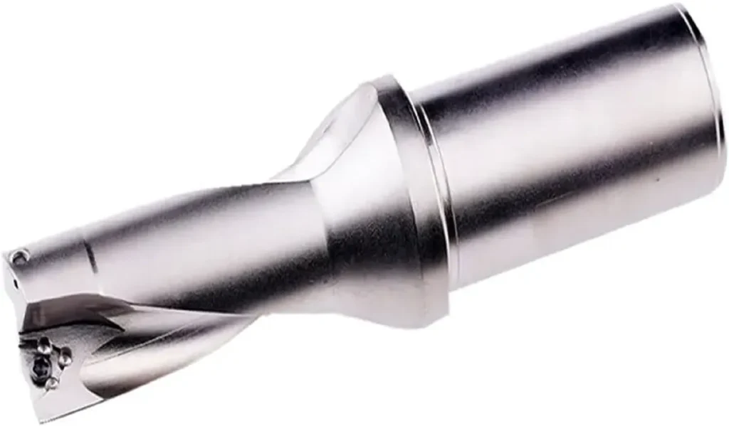
B. Indexable Insert Cutters
- Best For: Roughing, large diameters (>20mm / 0.75″), heavy material removal.
- The “True 90°” Challenge: Many standard shoulder inserts actually cut at 89.5° or have a slight taper to protect the insert tip.
- Solution: If the print requires strict perpendicularity, ensure you specify “High Precision 90°” or “True 90°” bodies and inserts, or leave 0.5mm (0.020″) stock for a solid carbide finisher.

C. Extended Flute / Corn Cob Cutters
- Best For: Deep shoulders (Depth > 3x Tool Diameter).
- Pain Point: High vibration susceptibility.
- Strategy: Use inserts with Chip Splitter geometry to break cutting forces, significantly reducing power consumption and chatter.
Critical Techniques: Climb vs. Conventional Milling
From an engineering perspective, the core distinction between Climb and Conventional milling lies in the Chip Thickness Variation Rate and the resulting physics of the Shear Plane.
A. Climb Milling (Down Milling) – The Ideal Shear State
In Climb Milling, the cutter rotates in the same direction as the feed.
- Chip Formation Mechanics (Thick-to-Thin):
- The tooth engages the material at maximum chip thickness ($h_{max}$). This means the tool immediately bites into the metal, initiating shear deformation instantly.
- Zero Rubbing: Because there is no “buildup” phase, the cutting edge does not slide across the surface, effectively eliminating work hardening.
- Thermodynamics:
- The majority of cutting heat is generated in the shear zone. Since the chip forms thick and fast, the heat is concentrated within the chip itself and ejected. The workpiece and tool remain relatively cool.
- Force Vector Analysis:
- The vertical component of the cutting force points downward. This presses the workpiece into the table or fixture (increasing system rigidity) and dampens vibration in thin-plate machining.
- Failure Mode:
- Primarily predictable flank wear.
B. Conventional Milling (Up Milling) – The Battle of Friction
In Conventional Milling, the cutter rotates against the feed direction.
- Chip Formation Mechanics (Thin-to-Thick):
- Upon contact, the theoretical chip thickness is zero. The tool cannot cut immediately; instead, it undergoes a phase of Rubbing and Ploughing.
- Critical Thickness: True shearing only begins once the accumulated pressure exceeds the material’s yield strength. Before this point, the material is subjected to intense compression and friction.
- Thermodynamic Disaster:
- The rubbing phase generates extreme frictional heat. This heat is transferred directly into the workpiece surface (causing thermal distortion) and the tool edge (accelerating wear).
- Work Hardening: For Stainless Steel and Superalloys, the rubbing effect instantaneously hardens the surface skin, forcing the subsequent tooth to cut into harder material—a vicious cycle.
- Force Vector Analysis:
- The vertical force component points upward, attempting to lift the workpiece off the table. This demands exceptional clamping force.
C. Decision Matrix: When to Break the Rule?
Although 95% of shoulder milling should use Climb Milling, specific engineering scenarios demand Conventional Milling:

| Scenario | Physics / Reason | Recommended Strategy |
|---|---|---|
| Cast Iron / Forging Scale | Climb milling forces the edge to impact hard, abrasive scale. Conventional allows the tool to cut from the soft inner matrix outwards, popping the scale off. | Use Conventional for Roughing |
| Backlash (Manual Machines) | On machines without ball screws, Climb milling pulls the table into the cutter, causing unpredictable feed and breakage. Conventional provides resistance to eliminate play. | Must use Conventional |
| Thin Wall Correction | Climb forces push the tool away (increasing wall thickness); Conventional forces pull the tool in (undercutting). | Alternate Climb/Conv passes to balance deflection. |
Entry Strategies
Stop Plunging! Never plunge a standard shoulder mill straight down like a drill. This destroys the bottom edges.
- Ramping: Enter at a 3°-5° slope along the cut path.
- Helical Interpolation: The best method for opening pockets or creating starter holes.
Dynamic Milling Guide
For deep shoulders (e.g., 30mm depth, 15mm width), the traditional strategy is to take multiple shallow depth passes (e.g., 3mm per pass). This method is inefficient and utilizes only a fraction of the tool’s cutting edge.
The modern engineering standard is Trochoidal / Dynamic Milling.
A. Why Traditional Shoulder Milling Fails in Corners
When a tool follows a straight path into a 90° internal corner:
- Engagement Angle Spike: The contact angle between the tool and material jumps from 50% (90 degrees) to 100% (180 degrees) instantaneously.
- Load Overload: Cutting forces double, causing severe chatter and vibration.
- Heat Trap: Coolant cannot penetrate the corner, and chips are trapped, leading to catastrophic edge failure.
B. The Core Logic of Dynamic Milling
Dynamic milling uses algorithms to constantly adjust the tool path (often spiral or peeling motions) to maintain a Constant Engagement Angle.
- Low Ae (Width): Always maintains a minimal radial depth (typically 5-10%).
- High Ap (Depth): Utilizes 200%-300% of the tool diameter, leveraging the entire flute length of solid carbide end mills.
- Result: Constant tool load and rapid heat evacuation allow for incredible feed rates.
C. Practical CAM Setup Guide (Step-by-Step)
Setup guide for Mastercam (Dynamic), Fusion 360 (Adaptive Clearing), or NX (Adaptive Milling):
Step 1: Maximize Axial Depth of Cut (Ap)
- Setting: Set to 90% – 95% of the tool’s flute length.
- Reason: Distributes wear evenly along the entire cutting edge rather than concentrating it at the tip.
Step 2: Optimize Radial Width of Cut (Ae – Optimal Load)
- Setting: Set to 8% – 12% of tool diameter (Steel) or 15% – 20% (Aluminium).
- Warning: Do not exceed 25%, or the Radial Chip Thinning effect diminishes, and heat will spike.
Step 3: Calculate Feed Rate Compensation. This is the most overlooked yet critical step in dynamic milling. Because the Radial Width of Cut ($Ae$) is minimal, the actual chip thickness becomes much thinner than the programmed feed due to Radial Chip Thinning (RCT). If uncompensated, the tool will “rub” rather than “cut”.
The Core Formula

- Variable Definition:
- F(new) (Compensated Feed Rate): The actual programming feed rate you enter into the CNC or CAM (mm/min or mm/z).
- F(normal) (Standard Feed Rate): The original feed per tooth recommended by the manufacturer for the material (mm/z). E.g., 0.05 mm/z.
- Ae (Radial Width/Stepover): The side stepover amount set in Step 2 (mm).
- Dc (Tool Diameter): The nominal diameter of the cutter (mm).
- Calculation Case Study:
- Scenario: Machining Stainless Steel with a φ12mm End Mill.
- Manufacturer Rec (Fnormal): 0.05 mm/z.
- Stepover Setting (Ae): 0.6mm (5% of Diameter).
- Calculation Steps:
- Calculate Radial Ratio (Ae/Dc): 0.6 / 12 = 0.05
- Calculate Thinning Factor(√0.05)≈0.2236
- Apply Formula: (√0.05)≈0.2236
- Final Result (F-new): You should program 0.22 mm/z, not 0.05 mm/z.
- Conclusion: The feed rate is increased by 4.4x, yet the tool still experiences a safe 0.05mm chip load.
Step 4: Set Minimum Trochoidal Radius
- Setting: Set to 10% – 20% of the tool diameter.
- Reason: Prevents the tool from making sharp “stop-and-turn” motions in corners, maintaining fluid machine motion.
Step 5: Micro-Lifts
- Setting: Set a 0.2mm – 0.5mm lift on non-cutting back moves.
- Reason: Prevents the bottom of the tool from dragging on the finished floor during retraction, eliminating heat buildup.
Avoiding “Mismatch” Lines
When a shoulder is deeper than your flute length (e.g., 100mm deep) and you must take multiple depth passes:
Tapered Walls: Leave a slight taper in roughing and perform a final full-depth spring pass to straighten the wall.
Wall Overlap: Set a 0.5mm overlap in CAM to blend the two depth passes.
Troubleshooting Guide
The “Golden Rules” for solving shop floor issues.
| Problem | Possible Cause | Solution |
|---|---|---|
| Vibration / Chatter | 1. Excessive overhang 2. Poor workholding 3. Ae (Width) too large | 1. Use variable helix end mills 2. Check balance 3. Reduce RPM, Increase Feed (adds damping) |
| Steps/Mismatch on Wall | 1. Tool Deflection 2. Insert seating error | 1. Add a “Spring Pass” (zero stock cut) 2. Check Spindle Runout |
| Poor Floor Finish | 1. Wiper edge wear 2. Feed per tooth too high | 1. Use inserts with Wiper geometry 2. Feed must be < 80% of wiper flat width |
| Burrs on Wall | 1. Dull tool 2. Improper exit strategy | 1. Change inserts/tool 2. Use a 45° Roll-off exit path |
| Chipping Edges | 1. Unstable cutting 2. Chip recutting | 1. Switch to a tougher grade 2. Use Air Blast (for Steel) to clear chips |
Material-Specific Tips & Strategies (ISO Groups)
A. ISO N – Aluminum & Non-Ferrous
- Core Challenge: Built-Up Edge (BUE) and Chip Evacuation. Aluminum is “sticky” and welds to the flute.
- Tool Geometry:
- Flute Count: 2 or 3 flutes. Large gullets are mandatory to handle high MRR.
- Helix Angle: High helix (45° or 55°) to pull chips vertically out of the cut.
- Coating: Must use Polished Flutes (Uncoated) or DLC/ZrN.
- Forbidden: NEVER use AlTiN or TiAlN coatings. The Aluminum affinity causes instant chip welding.
- Strategy: Max out RPM. Use high-pressure flood coolant primarily to flush chips, not just to cool.
B. ISO P – Carbon & Alloy Steels
- Core Challenge: Thermal Cracking and Crater Wear.
- The Coolant Paradox:
- Roughing: Strongly recommend AIR BLAST (Dry). Milling is an interrupted cut. Coolant causes “Thermal Shock” (rapid heating/cooling cycles), leading to micro-cracks in the carbide.
- Finishing: Use coolant (emulsion) to clear chips and improve surface finish, as heat generation is lower.
- Tooling:
- Coating: AlTiN or AlCrN. These form a protective Aluminum Oxide layer at high temperatures.
- Design: Variable helix/pitch to dampen harmonic vibration in harder steels.
C. ISO M – Stainless Steel (304/316)
- Core Challenge: Work Hardening, poor thermal conductivity, and toughness.
- Golden Rule: “Cut, don’t rub.”
- Strategy:
- Feed Rate (fz): Maintain a heavy feed per tooth (typically >0.05mm) to ensure the edge penetrates beneath the work-hardened skin. NEVER baby the tool with light feeds (e.g., 0.01mm), or it will glaze the surface.
- No Dwell: Keep the tool moving. Dwelling in corners causes instant localized hardening.
- Coolant: Rich emulsion (>8% concentration) is mandatory for lubricity and cooling.
- Milling Mode: Climb Milling is Mandatory. Conventional milling’s initial rubbing phase creates a hard skin immediately.
D. ISO S – Titanium & Superalloys
- Core Challenge: Heat Concentration. Titanium does not transfer heat into the chip; heat stays in the tool edge.
- Kinetic Strategy:
- Radial Depth (Ae): Limit to <30% of diameter. Leverage chip thinning to increase the contact length for heat dissipation.
- Arc-In: Always arc into the cut. Straight line entry shocks the brittle carbide edge.
- Speed Control: Extremely sensitive to Surface Speed (Vc). Usually capped at 60-100 m/min. Exceeding this destroys tool life instantly.
- Tool Features: High relief angles, high flute count (to increase table feed at low RPM), and large corner radii (re) for strength.
E. ISO K – Cast Iron
- Core Challenge: Abrasive Wear and Dust.
- Strategy:
- Dry Machining: Highly recommended with strong vacuum extraction. Iron dust + coolant = abrasive grinding paste (slurry) that destroys ways and tools.
- Coating: Thick CVD coatings (TiCN/Al2O3) or hard PVD coatings to resist abrasion.
- Entry: Cast iron often has a hard “skin” or scale. Use conventional milling for the first pass to cut from underneath the scale, or reduce feed by 20%.
Shoulder Milling Strategy Guide
Material-Specific Optimization Parameters (ISO 2025 Standard)
| ISO Group | Core Challenge | Tooling & Coating | Coolant Strategy | Critical Pro Tip |
|---|---|---|---|---|
| ISO N Aluminum / Non-Ferrous | Built-Up Edge (BUE) Sticky chips welding to flutes. | Polished / Uncoated 2-3 Flutes | High Pressure Flood | “Never use AlTiN coatings. The aluminum affinity causes instant failure.” |
| ISO P Carbon & Alloy Steels | Thermal Shock Rapid heating/cooling causes micro-cracks. | AlTiN / AlCrN Variable Helix | AIR BLAST (Dry) For roughing only | “Coolant during roughing kills carbide life. Run dry to keep heat in the chip.” |
| ISO M Stainless (304/316) | Work Hardening Surface hardens instantly if rubbed. | AlTiN / TiSiN High Relief Angle | Rich Emulsion (>8%) | “Cut, don’t rub. Never baby the feed rate (<0.05mm) or dwell in corners." |
| ISO S Titanium / Inconel | Heat Concentration Heat stays in the tool edge, not chip. | Sharp Edge High Flute Count | High Pressure Flood | “Limit radial width (Ae) to <30%. Always ARC-IN, never enter straight." |
| ISO K Cast Iron (Gray/Ductile) | Abrasive Wear Dust creates grinding slurry. | Thick CVD (TiCN) Strong Edge Prep | DRY + Vacuum | “Use conventional milling on the first pass to break through the hard casting skin.” |
Essential Formulas
Keep these handy for parameter adjustments:
- RPM Calculation (Vc = Surface Speed m/min, Dc = Tool Diameter mm)

- Table Feed (MMPM / IPM)(z = No. of Flutes, fz = Feed per tooth)

- Material Removal Rate (MRR)(ap = Depth of cut, ae = Width of cut)

Conclusion
Shoulder milling is deceptive. It appears to be a simple geometric operation, yet it represents one of the most complex balancing acts in CNC machining. As we have explored, success lies not in blindly following a catalog speed chart, but in understanding the underlying physics of Radial Force (Fr), Chip Formation Mechanics, and Thermal Management.
To consistently outperform competitors and achieve “skyscraper” quality results, remember these three pillars:
- Respect the Forces: Understand that the 90° lead angle creates massive radial deflection. Counteract this with the right tool geometry (variable helix), correct milling direction (Climb), and rigid workholding.
- Embrace Dynamics: Traditional static toolpaths are obsolete for deep shoulders. Dynamic Milling (HEM) allows you to utilize the full potential of your solid carbide tools, extending life by 300% or more while drastically reducing cycle times.
- Material Intelligence: Treat every material as a unique adversary. What works for Aluminum (High Speed, Flood Coolant) is catastrophic for Carbon Steel (Thermal Shock risk) or Stainless Steel (Work Hardening risk).
By applying the strategies, formulas, and troubleshooting protocols outlined in this guide, you are not just cutting metal—you are engineering a predictable, high-efficiency process.
Ready to optimize your production? Stop guessing parameters. Browse our High-Performance End Mill Series designed specifically for shoulder stability, or contact our application engineers for a custom toolpath consultation.