Why Multi-V Pulley Grooving Inserts Chip: Solving Thin-Wall Chatter and Surface Defects
When a carbide insert fractures during multi-V belt pulley grooving, the initial reaction on the shop floor is often to blame the tool grade or coating quality. However, practical machining dynamics reveal that tool breakage in these applications is rarely caused by carbide quality alone. Instead, the root cause is almost always thin-wall harmonic chatter induced by excessive radial cutting resistance and structural deflection.
In this technical breakdown, we analyze a real-world case study involving severe pulley surface vibration marks and insert edge chipping, providing actionable fixturing solutions and precise cutting parameters to stabilize your machining process.
1. The Machining Challenge: Vibration Marks & Chipping
In a recent customer application involving multi-ribbed pulley machining, two critical failures occurred simultaneously:
- Severe, regular chatter marks appeared across the grooved profile and outer diameter.
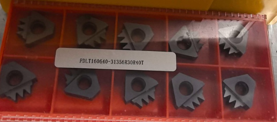
- Catastrophic edge chipping fractured the cutting teeth of the profile insert.
(Insert Image: Close-up of fractured multi-tooth poly v grooving inserts and chatter-marked pulley surface)
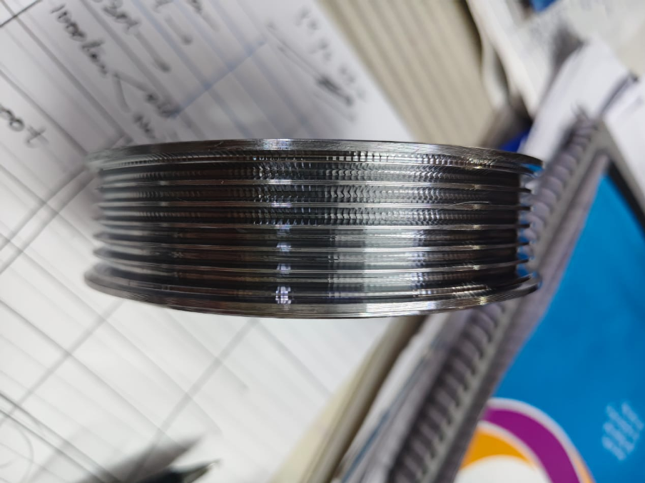
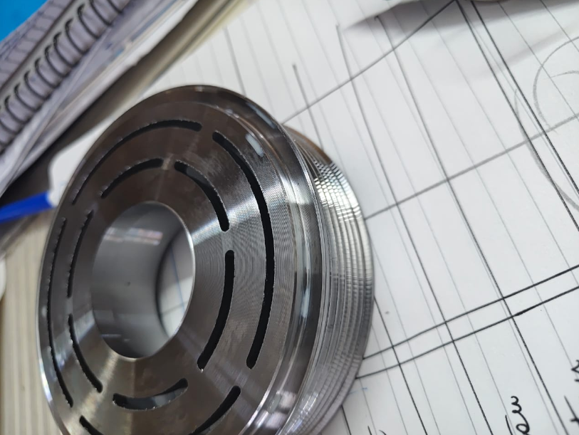
The pulley design features a deep internal weight-reduction cavity, leaving the outer grooved rim as an unsupported, thin-walled cantilever structure.
2. Root Cause Analysis
High Instantaneous Radial Load (Fp)
Multi-ribbed pulley form tools engage several V-grooves at the same time. When the insert plunges radially into the workpiece, the total contact length between the cutting edges and the workpiece spikes dramatically. This creates a massive radial thrust force acting perpendicular to the weakest axis of the part.
Cantilever Deflection & Resonance
Because the outer rim is thin and unsupported, this heavy radial force causes the wall to deflect elastically during cut entry. As the material springs back, it sets off regenerative chatter and high-frequency resonance.
Dynamic Impact on the Carbide Edge
Tungsten carbide offers exceptional hardness and wear resistance, but its transverse rupture strength is vulnerable to alternating dynamic impacts. The high-frequency hammering effect of the vibrating thin wall rapidly exceeds the edge toughness limit, causing micro-chipping that quickly escalates into full tooth breakage.
3. Engineering Countermeasures & Practical Parameters
Resolving this issue requires a dual approach: dampening workpiece deflection through mechanical support and relieving the cutting load with step-down infeed parameters.
Strategy A: Fixturing & Structural Support (Essential)
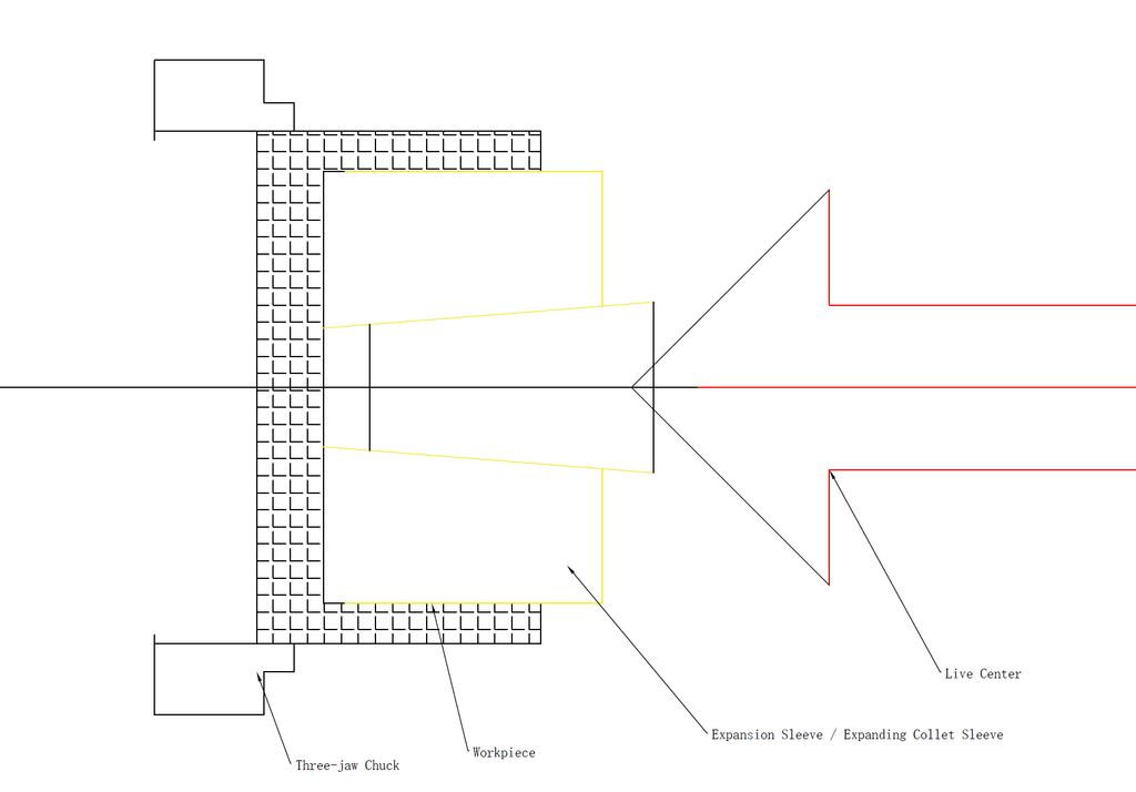
- For Small Batches / Job Shops (Tailstock Support):Engage a large-diameter live center or a custom stepped center in the lathe tailstock. Pressing firmly against the inner cavity lip or chamfer adds axial and radial preload, immediately suppressing cantilever fluttering.
- For High-Volume Production (Expanding Mandrels):Implement an internal expanding collet sleeve. As the sleeve expands against the inner wall, it locks the cantilever rim, eliminates vibration freedom, and provides structural damping throughout the grooving cycle.
(Insert Diagram: Tailstock live center and internal expanding sleeve schematics)
Strategy B: Step-Down Infeed & Optimized Cutting Parameters
To prevent overloading the tool edge and exciting thin-wall harmonics, adjust the feed per pass and cutting speed as follows:
- Cutting Speed (Vc): Maintain linear cutting speeds strictly between 100 m/min – 130m/min. This balanced speed range prevents high-frequency thermal softening while staying well outside the workpiece’s primary harmonic chatter pocket.
- Step-Down Radial Depth of Cut(ap):
- Roughing Phase: Set the radial depth of cut per pass to 0.07mm. This moderates the instantaneous radial cutting resistance while maintaining efficient chip formation.
- Finishing Phase: Drop the depth of cut per pass down to 0.05mm for the final sizing passes. Reducing the cutting depth to 0.05mm minimizes cutting pressure on the finished profile, eliminating surface micro-vibrations and ensuring a mirror-like groove finish.
- Roughing Strategy: For pulleys with deep grooves, use a standard single-point grooving insert to rough out the primary slots first. Save the multi-ribbed form tool exclusively for the final 0.07mm→ 0.05mm step-down finishing passes.
4. Summary & Best Practices
When form tools chip on thin-walled pulleys, blaming tool material quality is rarely the answer. Successful machining relies on the harmony between machine rigidity, workpiece clamping, and cutting data.
By applying internal support (such as live centers or expanding sleeves) and strictly managing the infeed parameters (100 – 130m/min linear speed with 0.07mm→0.05mm step-down depths), shops can completely eliminate chatter marks and achieve long, predictable insert tool life.
Need Custom Tooling or Process Optimization for Your Production?
Machining thin-walled pulleys and specialized profiles requires tailored cutting tool geometry matched with robust process support.
We engineer high-performance carbide grooving solutions:
- Custom Multi-V Pulley Inserts: Precision-ground profiles with edge preparations optimized for interrupted cuts and thin-wall applications.
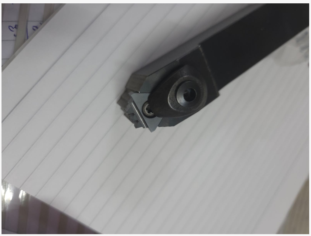
- High-Rigidity Toolholders: ISO-compliant and custom clamping blocks designed to minimize overhang deflection under heavy radial loads.
- Application Engineering Support: Share your component drawings and machine specs with our engineers for custom infeed recommendations, grade selection, and fixture advice.
👉 Contact Our Engineering Team today to resolve your shop-floor machining bottlenecks.