CNMM 插入
CNMM刀片角度:0° 負前角刀片與單面斷屑槽;。
80° 菱形車削刀片;
主要工件材料:不銹鋼、鋼、黃銅、青銅、鋁和鑄鐵;
斷路器應用:粗糙、重型、半刨削;
搭配車削工具座:PCBNR/L、PCLNR/L、MCLNR/L、MCBNR/L;
等級:CVD;
材質 : 碳化鎢
CNMM 插件規格
重切削和半重切削需要專為此任務設計的斷屑槽。寬型斷屑槽可在大切深、高進給時優化切屑控制。切削刃的強度可藉由平坦的負面設計達到最大化。相反地,精加工作業則可使用較小的斷屑槽,以減少切削力,進而利於斷屑。在精加工時,切削刃的鋒利度應以正刀刃及小刃口珩磨為優先.CNMM刀片適用於粗加工.
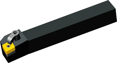
CNMM 刀片座
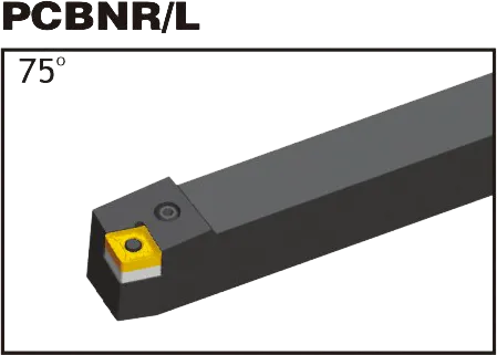


MCLNR/L
CNMM 插入簡介
1.尺寸
- 形狀: 內含 80 度角的菱形 (鑽石)。
- 淨空角度: 負值(通常在 -5 到 -7 度之間)。
- 容忍度: Medium ('M') 是典型的公差,但也可能存在其他公差以滿足特殊需求。
- 刻字圓圈 (IC): 決定整體刀片尺寸(常見:12.7mm、16mm)。
- 厚度: 影響強度和刀刃數(常見:4.76mm、6.35mm)。
- 轉角半徑: 影響強度和表面光潔度(常見:0.4mm、0.8mm、1.2mm)。
2.斷路器幾何圖
- 非常重要: 斷屑槽可塑造切屑的形成與斷裂方式,確保有效的切屑流動、刀具保護與工件光潔度。
- 特定製造商: 斷路器指定編入 CNMM 代碼("MM")。具體資訊請參閱製造商目錄。
- 匹配到操作: 請考慮
- 工件材料
- 切削深度(輕切與重切)
- 期望的完成度
3.孔配置
- 中央洞: 用於安全夾緊刀把。
- 無孔: 依賴其他夾持機制。
- 刀柄相容性: 刀片的孔型必須與刀把相匹配。
4.塗層和基板
- 塗層: 常見的類型包括 TiN、TiAlN、CVD 和 PVD。每種類型都提供不同的耐磨性、熱特性以及對各種材料的適用性。
- 基板: 塗層所鍍的基本碳化物材料。成分各異,提供韌性與耐磨性的權衡。
- 特定應用: 正確的等級對於最佳性能和刀具壽命至關重要。
CNMM 刀片尺寸 (ISO)
| ISO 認證 | 刻字圓圈 (IC) | 厚度 | 轉角半徑 |
|---|---|---|---|
| CNMM 120404 | 12.7 公釐(0.5 吋) | 4.76 公釐(0.187 吋) | 0.4 公釐(0.016 吋) |
| CNMM 120408 | 12.7 公釐(0.5 吋) | 4.76 公釐(0.187 吋) | 0.8 公釐(0.031 吋) |
| CNMM 120412 | 12.7 公釐(0.5 吋) | 4.76 公釐(0.187 吋) | 1.2 公釐(0.047 吋) |
| CNMM 160608 | 16 公釐(0.63 吋) | 6.35 公釐(0.25 吋) | 0.8 公釐(0.031 吋) |
範例:CNMM 120408
- 菱形 (鑽石) 形狀,內含 80 度角
- 負間隙角
- 在「MM」標誌內的製造商特定詳細資訊
- 12 公釐刻字圓直徑(以英吋計約 0.47 吋)
- 4mm 厚(以英吋計約 0.157 吋)
- 0.8mm 機頭半徑 (約 0.031″ 英寸)
硬質合金刀片背後的科學:鎢鋼刀片的製造過程及強度原因
硬質合金刀片是目前用途最廣且最耐用的切削工具。但它們是如何製成的呢?是什麼讓它們如此堅固?在本影片中,我們將探討硬質合金刀片背後的科學,從碳化鎢的特性到製造過程。
我們的生產能力