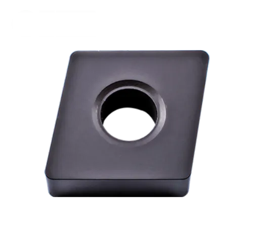
Shape: Rhombic (diamond) with an 80-degree included angle.
Clearance Angle: 0 degrees
Cutting Edges: Double-sided, offering two cutting edges per insert for cost-effectiveness.
Chipbreaker Geometries: Diverse range of chipbreaker styles from various manufacturers are available. These are tailored to specific materials and machining operations (roughing, finishing, etc.).
Key Uses: Primarily used for general turning operations and some facing work on a range of materials.
Common Materials CNMA Inserts are Used For
Cast Iron: Suitable for many cast iron applications.
Advantages of CNMA Inserts
Cost-effective: Due to their double-sided design, offering longer tool life per insert.
Versatile: The range of grades and chipbreakers make them suitable for many machining applications.
Strong Geometric Shape: The 80-degree diamond shape provides strength and rigidity for their size.
Important Considerations
Match the Grade to Your Material: Choosing the right insert coating and substrate composition is crucial for optimal tool life and performance in the specific material you’re cutting.
Select the Right Chipbreaker: The chipbreaker geometry significantly influences how chips are formed and broken. It should be chosen based on the material and type of machining operation.
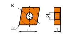
CNMA Insert Dimensions (ISO)
TYPE
CNMA INSERT DIAMENTIONS(mm)
LE
IC
S
DI
RE
CNMA120404
12.9
12.7
4.76
5.16
0.4
CNMA120408
12.9
12.7
4.76
5.16
0.8
CNMA120412
12.9
12.7
4.76
5.16
1.2
CNMA120416
12.9
12.7
4.76
5.16
1.6
CNMA160608
16.1
15.875
6.35
6.35
0.8
CNMA160612
16.1
15.875
6.35
6.35
1.2
CNMA160616
16.1
15.875
6.35
6.35
1.6
CNMA190612
19.3
19.05
6.35
7.94
1.2
CNMA190616
19.3
19.05
6.35
7.94
1.6
Example: CNMA 120408
12: Inscribed Circle (IC) of 12.7mm (approx. 0.5 inches)
04: Thickness of 4.76mm (approx. 0.187 inches)
08: Corner radius of 0.8mm (approx. 0.031 inches)
Key Dimensions
Inscribed Circle (IC): The diameter of the largest circle that fits within the insert. Common IC sizes include:
12.7mm (0.5″)
16mm (0.63″)
19.05mm (0.75″)
Thickness: Impacts insert strength and the number of usable cutting edges. Common thicknesses include:
3.18mm (0.125″)
4.76mm (0.187″)
6.35mm (0.25″)
Corner Radius: Affects surface finish and strength at the cutting edge. Common sizes include:
The Science Behind Carbide Inserts: How They're Made and Why They're So Strong
Carbide inserts are some of the most versatile and durable cutting tools available. But how are they made? And what makes them so strong? In this video, we’ll explore the science behind carbide inserts, from the properties of tungsten carbide to the manufacturing process.
Our Production Capability
Find the Perfect CNMA Insert for Your Application – Get Expert Help!