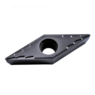
The insert is mainly used for semi-finishing or finishing applications.
The diamond shape with a 35 degree top angle has the widest accessibility and provides the best surface finish when machining out of round.
With our proprietary coating, the insert is suitable for most materials.
Key Features
Shape: VCMT inserts feature a 35° rhombic (diamond) shape, giving them four cutting edges for cost-effectiveness. This narrower angle enhances strength at the cutting tip.
Positive Rake Angle: The cutting face slopes slightly forward from the cutting edge. This often produces a smoother cut with lower cutting forces, suitable for softer materials or low-power machines.
Clearance Angle: Typically 7° to help prevent rubbing against the workpiece.
Chipbreakers: VCMT inserts feature various chipbreaker geometries to control chip formation and flow.
Coatings: Often coated with materials like TiN, AlTiN, etc., to improve wear resistance and tool life.
VCMT insert Specification
Understanding the Insert Code
V: Shape. Rhombic (diamond) with a 80-degree included angle. C: Clearance Angle. 7 degrees (positive). M: Tolerance. Typically medium tolerance, but other options might be available. T: Chipbreaker style & Hole Configuration. This letter identifies the specific chipbreaker geometry and hole presence/absence. Chipbreaker variations are numerous and manufacturer-specific.
Numerical Digits: First Two Digits: Inscribed circle (IC) diameter in millimeters. To obtain the approximate inch equivalent, divide this number by 25.4. Next Two Digits: Thickness in millimeters. Divide by 25.4 to convert to inches. Last Two Digits: Nose radius in millimeters. To convert to inches, divide by 25.4.
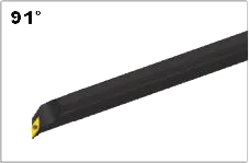
VCMT insert holder(Boring bar)
SVQBR/L
SVUBR/L
Carbide VCMT Insert Dimensions (ISO)
Designation
Inscribed Circle (IC)
Thickness
Corner Radius
VCMT 110302
11mm (0.43")
3.18mm (0.125")
0.2mm (0.008")
VCMT 110304
11mm (0.43")
3.18mm (0.125")
0.4mm (0.016")
VCMT 160404
16mm (0.63")
4.76mm (0.187")
0.4mm (0.016")
VCMT 160408
16mm (0.63")
4.76mm (0.187")
0.8mm (0.031")
Example: VCMT 160408 (ISO)
Rhombic (diamond) shape with an 80-degree included angle
7-degree positive clearance angle
Medium tolerance
Manufacturer-specific chipbreaker and hole configuration
16mm inscribed circle diameter (approx. 0.63″ in inches)
The Science Behind Carbide Inserts: How They're Made and Why They're So Strong
Carbide inserts are some of the most versatile and durable cutting tools available. But how are they made? And what makes them so strong? In this video, we’ll explore the science behind carbide inserts, from the properties of tungsten carbide to the manufacturing process.
Our Production Capability
In modern manufacturing, high-performance carbide inserts are indispensable tools, laying the foundation for efficient and precise metal processing. However, these exceptional inserts do not come into existence on their own; they are supported by the unwavering support of advanced machinery.
Find the Perfect VCMT Insert for Your Application – Get Expert Help!