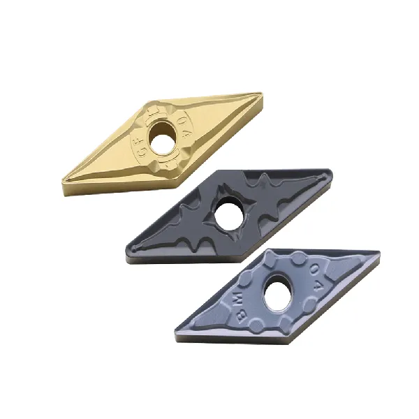
The VCGT insert is specially designed for aluminium alloy lathe machining, with a dedicated chipbreaker, which not only eliminates the problem of chip entanglement that occurs during aluminium alloy finishing, but also provides an excellent surface finish.
Key Features
Shape: VCCT inserts feature an 80° rhombic (diamond) shape, giving them four cutting edges which provides cost-effectiveness.
Positive Rake Angle: The cutting face slopes slightly forward from the cutting edge. This often produces a smoother cut with less cutting force, suitable for specific material types.
Clearance Angle: Typically around 7° to help prevent rubbing against the workpiece.
Sharp Cutting Edge: The acute corner radius promotes better surface finishes, especially for finishing operations.
Chipbreakers: VCGT inserts may have chipbreakers on one or both sides to influence chip formation and control.
Coatings: Often coated with materials like TiN, AlTiN, etc., to improve wear resistance and tool life.
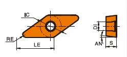
VCGT insert Specification
Understanding the VCGT Code
The letters and numbers in the VCGT designation tell you about the insert:
V: 80° rhombic shape
C: 7° clearance angle
G: Indicates the specific hole and chipbreaker design (varies by manufacturer)
T: Indicates tolerance class (precision of size)
Numbers:
Typically, the first two numbers represent the inscribed circle (size of the diamond) in sixteenths of an inch (or directly in millimeters for ISO codes).
The third number represents thickness in sixteenths of an inch.
The last number often indicates the nose radius (smaller means sharper).
The Science Behind Carbide Inserts: How They're Made and Why They're So Strong
Carbide inserts are some of the most versatile and durable cutting tools available. But how are they made? And what makes them so strong? In this video, we’ll explore the science behind carbide inserts, from the properties of tungsten carbide to the manufacturing process.
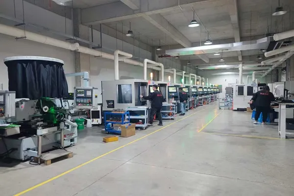
Our Production Capability
Find the Perfect VCGT Insert for Your Application – Get Expert Help!