Talaş kırıcı, genellikle uzun metal talaşları daha kısa parçalara ayıran bir oluk olarak tanımlanır. Bu tanım doğrudur, ancak eksiktir.
Pratik olarak kesici uç seçiminde, talaş kırıcı şu şekilde anlaşılmalıdır: tamamen son teknoloji ürünü geometri. Genellikle kesici kenarın çevresindeki üst yüzey oluğu, eğim açısı, düzlük veya pah, kenar honlaması ve diğer özellikleri bir araya getirir.
Bu özellikler birbiriyle uyumlu bir şekilde çalışarak üç unsuru kontrol eder:
- Çip oluşumu ve tahliyesi;
- Kesme kuvvetleri ve ısı oluşumu;
- Son derece yüksek mukavemet ve ufalanmaya karşı direnç.
Bu nedenle, en iyi talaş kırıcı her zaman mümkün olan en kısa talaşları üreten geometri değildir. Kabul edilebilir kesme kuvvetlerini, yüzey kalitesini ve takım ömrünü korurken, işlenebilir talaşlar üreten geometridir.
Kısa cevap: Talaş kırıcıyı, işleme işlemi, iş parçası malzemesi, ilerleme hızı ve kesme derinliğine uygun olarak seçin. Ardından, kesme işleminin istikrarı için kenar hazırlığı ve kesici uç kalitesinin yeterince sağlam olup olmadığını kontrol edin.
Bu kılavuz öncelikle şu konulara odaklanmaktadır: değiştirilebilir tornalama uçları. Aynı temel ilkeler, oluk açma, kesme ve frezeleme kesici uçları için de geçerlidir; ancak kesme koşulları ve üreticilerin seçim tabloları farklıdır.
Ekleme Tipi Talaş Kırıcı Nedir?
En dar anlamıyla, talaş kırıcı, kesme uçunun kesme yüzünde oluşturulan bir oluk, basamak veya çıkıntılı yapıdır. Amacı, talaş kırılana veya kesme bölgesinden güvenli bir şekilde uzaklaşana kadar talaşı yeniden yönlendirmek ve kıvırmaktır.
Ancak, modern ekleme üreticileri Genellikle talaş kırıcıyı, eksiksiz bir geometri paketinin bir parçası olarak tasarlarlar.
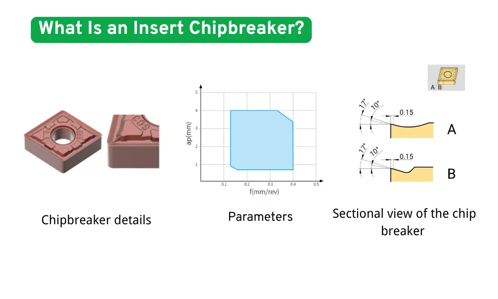
Bir Talaş Kırıcı Geometrisinin Temel Unsurları
| Geometri elemanı | İşlev |
|---|---|
| Kesici oluk genişliği | Çipin kıvrılmaya zorlanmadan önce ne kadar uzağa ilerleyeceğini belirler |
| Yiv derinliği veya duvar yüksekliği | Çipin ne kadar güçlü bir şekilde yönlendirileceğini belirler |
| Tırmık açısı | Çip akışını, kesme kuvvetini ve ısı oluşumunu etkiler |
| En son teknolojiyle donatılmış arazi | Kesici kenarın hemen arkasında destek sağlar |
| Arazi açısı veya T-arazi | Daha ağır veya kesintili kesimler için kenarı güçlendirir |
| Kenar bileme | Kenarı yuvarlayarak ve güçlendirerek mikroçentik oluşumunu azaltır |
| Yerel çıkıntılar veya çukurlar | Belirli kesme bölgelerinde yongayı düz yönlendirin, bölün veya kıvrılmasını sağlayın |
| Parlatılmış tırmık yüzeyi | Alüminyum ve diğer demir içermeyen malzemelerde yapışmayı azaltır |
Bu özellikler birbirinden bağımsız olarak değerlendirilemez. Örneğin, oldukça büyük bir eğim açısı kesme kuvvetlerini azaltabilir, ancak bu durum genellikle kesme kenarını destekleyen malzeme miktarını azaltır. Daha geniş bir kenar boşluğu veya daha ağır bir kenar taşlama işlemi, kenar mukavemetini artırır, ancak aynı zamanda kesme basıncını da artırabilir.
Bu nedenle, talaş kırıcı seçimi bir denge kurma çalışmasıdır:
- çip kontrolü;
- kesilme direnci;
- kenar mukavemeti;
- yüzey kalitesi;
- işlem kararlılığı.
Çip Kontrolü Neden Önemlidir?
Yetersiz talaş kontrolü, makine muhafazasının dağınık kalmasından çok daha ciddi sorunlara yol açabilir.
Uzun, kesintisiz talaşlar şunları sağlayabilir:
- iş parçasının, ek parçanın veya takım tutucunun etrafını sarmalayın;
- bitmiş bir yüzeyi çizmek;
- soğutma sıvısı akışını engellemek;
- bir yonga konveyörünü tıkamak;
- otomatik takım değişimlerini engellemek;
- hortumlara, prob'lara veya yakınındaki aletlere zarar verebilir;
- operatörü makineyi durdurmaya zorlamak;
- keskin ve tehlikeli yol tutuş koşullarına yol açar.
Otomatik tornalama, gözetimsiz işleme ve yüksek hacimli üretimde, tek bir talaş kontrolündeki arıza, aksi takdirde istikrarlı seyreden bir süreci durdurabilir.
Uygun bir talaş kırıcı, talaşı kıvrılmasını sağlayarak ve yönlendirerek, takım veya parçaya zarar vermeden kesme bölgesinden çıkabilecek bir şekle sokmaya yardımcı olur. Sandvik, torna işlemlerinde talaş kontrolünü etkileyen başlıca faktörler olarak talaş kırıcı geometrisini, ilerleme hızını, kesme derinliğini ve burun yarıçapını belirlemektedir.
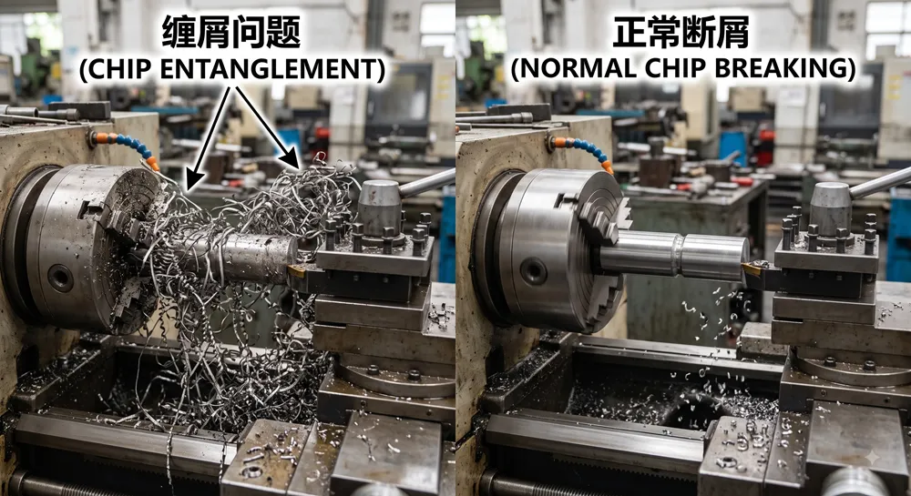
Bir talaş kırıcının üç temel görevi vardır
1. Çipi kontrol edin
Geometri, talaşı bükerek, kıvırarak ve yönlendirerek, talaşın kırılmasını veya güvenli bir şekilde dışarı atılmasını sağlar.
2. Kesme kuvvetlerini kontrol etmek
Tırmık yüzeyi ve kenar geometrisi, iş parçası malzemesinin kesici uç üzerinden ne kadar kolay akacağını belirler. Daha keskin ve pozitif bir geometri genellikle daha az kuvvetle kesim yaparken, daha sağlam bir geometri genellikle daha fazla kuvvet gerektirir.
3. Kesici kenarı koruyun
Yüzey, pah ve kenar taşlama mekanik destek sağlar. Bu özellikler özellikle kaba işleme, kesintili kesme, kireç giderme ve dengesiz işleme sırasında önemlidir.
Bu nedenle, bir talaş kırıcı asla sadece şu soruyu sorarak seçilmemelidir:
“Bu geometri çipi bozacak mı?”
Asıl sorulması gereken soru şudur:
“Yeterli kenar mukavemeti, takım ömrü ve yüzey kalitesini korurken çipi kontrol edebilecek mi?”
Talaş Kırıcı, Talaşı Nasıl Kırar?
Talaş oluşumu, kesici kenarın iş parçasından malzemeyi keserek ayırmasıyla başlar. Yeni oluşan talaş, kesici uçun eğimli yüzü boyunca ilerler.
Bir talaş kırıcı, talaşın yönünü ve eğriliğini dört temel aşamada değiştirir.
1. Çip oluşumu
Malzeme iş parçasından kesilerek ayrılır ve kesme yüzeyi boyunca akmaya başlar.
2. Yonga kıvrılması
Yiv, duvar veya yükseltilmiş geometri, talaşın daha küçük bir yarıçap üzerinden bükülmesine neden olur.
3. Gerilim birikimi
Çip kıvrıldıkça, kalınlığı boyunca eğilme gerilimi oluşur.
4. Çip ayrıştırma
Gerilim yeterince yüksek bir seviyeye ulaştığında ya da kıvrılmış yonga başka bir yüzeyle temas ettiğinde, yonga kırılır.
Yaygın Çip Kırılma Şekilleri
Bir çip çeşitli şekillerde kırılabilir.
Kendiliğinden frenleme
Çip, kendi eğriliği ve bükülme gerilimi nedeniyle kırılır.
Ek parçaya çarpma
Kıvrılan talaş, talaş kırıcı duvarına veya kesici uçun başka bir kısmına temas eder ve kırılır.
İş parçasına çarpma
Talaş, iş parçası yüzeyine doğru kıvrılır ve temas ettikten sonra kırılır.
En uygun çalışma şekli, yapılan işleme göre değişir. İş parçasıyla talaşın temas etmesi bazı kaba işleme işlemlerinde kabul edilebilir olsa da, ince işleme sırasında yüzeye zarar verebilir.
İyi Bir Cips Nasıl Olur?
En kısa fiş her zaman en iyi fiş değildir.
İyi bir yonga genellikle şu özelliklere sahiptir:
- alet veya bileşenin etrafına dolanmayacak kadar kısa;
- keskin ve sıcak parçacıklara dönüşmeyecek kadar uzun süre;
- soğutma sıvısı ve talaş konveyörünün kolayca çıkarılabilmesi;
- işlenmiş yüzeyden uzağa yönlendirilmiş;
- kesim boyunca tutarlı.
Genel olarak kabul edilebilir şekiller şunlardır:
- kompakt C şeklindeki yongalar;
- kısa sarmal talaşlar;
- doğal olarak kırılan, birkaç turlu sarmal talaşlar.
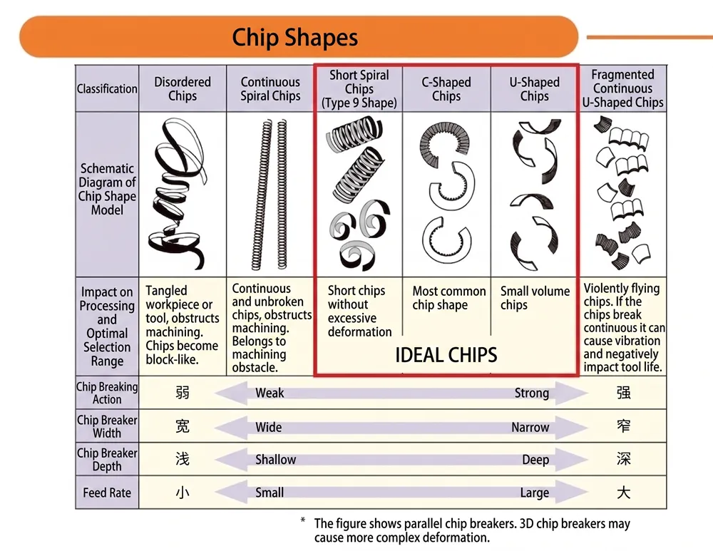
Teşhis Aracı Olarak Çipin Görünümü
| Çipin görünümü | Muhtemel yorum |
| Uzun, kesintisiz diziler | Talaş çok ince, kesici devreye girmiyor veya geometri çok açık |
| Büyük, gevşek spiraller | Çip kontrolü zayıftır, ancak tahliye güvenilir olduğu sürece yine de kabul edilebilir olabilir |
| Kompakt C şeklindeki yongalar | Genellikle talaş kırma ve uzaklaştırma arasında iyi bir denge sağlanır |
| Kısa sarmal talaşlar | Kesme bölgesinden tutarlı bir şekilde çıktıkları zaman genellikle kabul edilebilir |
| Çok küçük sert parçalar | Çip tutma kuvveti veya kesme yükü aşırı olabilir |
| Mavi veya aşırı derecede oksitlenmiş yongalar | Yonga sıcaklığı yüksek; bu her zaman bir sorun anlamına gelmez, ancak kesme koşulları kontrol edilmelidir |
| Birbirine kaynaklanmış yongalar | Kenarda birikme olasılığı, talaş tahliyesinin yetersizliği veya uygun olmayan hız |
| Düzensiz yonga uzunlukları | Değişken kesme derinliği, kesintili temas, dengesiz kurulum veya malzeme farklılıkları |
Son derece ince talaşlar, her zaman başarılı talaş kontrolünün bir göstergesi değildir. Bu durum, kesici kenarda aşırı yük olduğunu gösterebilir ve talaş kopması, krater aşınması veya yüzey hasarı riskini artırabilir.
Pratik hedef şudur:
Ne çok uzun ne de gereksiz yere kısa olan ve kesme bölgesinden güvenli bir şekilde çıkan talaşlar.
Talaş Kırıcı Kodları Üreticiye Özeldir
En önemli satın alma kurallarından biri, talaş kırıcı soneklerinin genellikle üreticiler arasında genel bir durum değildir.
Aşağıdaki gibi kodlar:
- PF;
- Başbakan;
- Halkla İlişkiler;
- Milletvekili;
- MF;
- MR;
- SM;
- GM;
- LF;
bunlar, son işlem, orta işlem, kaba işleme veya belirli bir malzeme grubunu ifade edebilir; ancak bunların tam anlamı ve çalışma aralığı üreticiye göre değişir.
A CNMG Torna Ucu İki farklı tedarikçinin ürünleri, aynı ISO şekil ve boyut koduna sahip olsalar da, tamamen farklı talaş kırıcı geometrisi, kenar hazırlığı ve önerilen kesme aralığı kullanabilir.
Her iki sonek de aynı harfi içerdiği için iki ekleme işleminin birbirine eşdeğer olduğunu varsaymayın M, F veya R.
Her zaman karşılaştırın:
- ek parçasının tam tanımı;
- üretici;
- iş parçası malzemesi önerisi;
- besleme aralığı;
- kesme derinliği aralığı;
- kenar hazırlığı;
- notu girin;
- tutucu ve giriş açısı.
[İç bağlantı: Döner Uç Kodunu Okuma Yöntemi]
Talaş Kırıcı ve Kesici Uç Sınıfı Karşılaştırması
Talaş kırıcı ve kesici uç kalitesi, birbirinden farklı ancak birbirini tamamlayıcı işlevler görür.
Talaş kırıcı, kesici uçun nasıl kesim yapacağını belirler
Etkilediği kişiler:
- çip akışı;
- kesme kuvveti;
- kenar keskinliği;
- çip kontrol aralığı;
- son derece yüksek mukavemet;
- son işlem veya kaba işleme için uygunluk.
Sertlik derecesi, kesici uçların ne kadar dayanıklı olacağını belirler
Karbür alt tabaka ve kaplama şunları etkiler:
- aşınma direnci;
- dayanıklılık;
- ısı direnci;
- plastik deformasyona karşı direnç;
- termal çatlamaya karşı direnç;
- iş parçası malzemesiyle kimyasal uyumluluk.
Aşırı derecede kırılgan bir kesici sınıfa takılan sağlam bir kaba işleme talaş kırıcı bile, kesintili bir kesim sırasında yine de arızalanabilir. Çok dayanıklı bir kesici sınıfı ise, keskin bir ince işleme geometrisini, tasarlanan aralığın çok ötesindeki bir ilerleme hızı veya kesme derinliğinden tam olarak koruyamayabilir.
Bu nedenle üreticiler, talaş kırıcıyı ve kesici uç kalitesini bir sistem olarak çalışacak şekilde tasarlar. Örneğin Haas, talaş kırıcının işleme türüne göre, kesici uç kalitesinin ise malzemeye ve kesme kararlılığına göre seçilmesini önerirken, bu iki seçimin birbirini tamamladığını da belirtir.
Kesici Ucu Kırıcı Nasıl Seçilir?
Bir geometriyi yalnızca görünüşüne veya adına göre seçmek yerine, aşağıdaki seçim sırasını kullanın.
1. Adım: İşleme İşlemini Belirleyin
Öncelikle işlemin aşağıdakilerden hangisi olduğunu belirleyin:
- son işlem;
- hafif kesim;
- orta veya genel tornalama;
- kaba işleme;
- ağır kaba işleme;
- sürekli;
- hafifçe kesintiye uğradı;
- sürekli kesintiye uğradı.
Bu işlem, keskinlik ile kesici kenar mukavemeti arasında gerekli dengeyi sağlar.
2. Adım: İşlenecek Parçanın Malzemesini Belirleyin
ISO iş parçası-malzeme grubunu başlangıç noktası olarak kullanın:
- ISO P: çelik;
- ISO M: paslanmaz çelik;
- ISO K: dökme demir;
- ISO N: demir dışı malzemeler;
- ISO S: ısıya dayanıklı süper alaşımlar ve titanyum;
- ISO H: sertleştirilmiş malzemeler.
Sadece malzeme grubu yeterli değildir. Ayrıca şunları da doğrulayın:
- tam alaşım;
- sertlik;
- ısı işlemi durumu;
- dövme, haddelenmiş veya döküm yüzey;
- sertleşme eğilimi;
- aşındırıcılık;
- birikmiş kenar oluşma eğilimi.
3. Adım: Besleme ve Kesme Derinliğini Belirleyin
Her talaş kırıcının bir çalışma aralığı vardır.
Üretici seçim tablolarında genellikle şu bilgiler gösterilir:
- devir başına besleme,
fn, bir eksende; - kesme derinliği,
ap, diğer eksende.
Kesme koşulları, önerilen talaş kontrol aralığı içinde olmalıdır.
Orta düzey tornalama için tasarlanmış bir talaş kırıcı, ilerleme hızının çok düşük olduğu durumlarda talaşı kıramayabilir; çünkü talaş, kırıcıya doğru şekilde temas edemeyecek kadar incedir. İlerleme hızı ve kesme derinliği önerilen aralığın çok üzerinde ise, aynı geometri kesici kenara aşırı yük bindirebilir.
4. Adım: Kesme Kararlılığını Değerlendirin
İşlemin aşağıdakileri içerip içermediğini kontrol edin:
- kesintili yüzeyler;
- anahtar yuvaları veya çapraz delikler;
- döküm veya dövme kaplama;
- kararsız iş parçası tutma;
- uzun alet çıkıntısı;
- ince bileşenler;
- makine gücünün yetersizliği;
- titreşim;
- kesme derinliğinin değiştirilmesi.
Kararsız koşullar genellikle şunları gerektirir:
- daha sağlam bir kenar hazırlığı;
- daha güvenli bir ek parça şekli;
- daha sert bir karbür kalitesi;
- denetlenmiş kesme verileri.
5. Adım: Burun Yarıçapını ve Giriş Açısını Kontrol Edin
Burun yarıçapı ve takım giriş açısı değişir:
- deforme olmamış yonga kalınlığı;
- çip genişliği;
- çip akış yönü;
- radyal ve eksenel kesme kuvvetleri;
- titreşim eğilimi.
Bir tutucu açısında iyi performans gösteren bir talaş kırıcı, aynı kesici uç başka bir tutucuya takıldığında farklı bir davranış sergileyebilir.
Çip kırıcıyı, tam takım grubundan ayrı olarak değerlendirmeyin.
6. Adım: Soğutma Suyu Durumunu Kontrol Edin
Kontrol edin:
- kuru veya ıslak işleme;
- soğutma sıvısı taşması;
- soğutma sıvısı akış yönü;
- takım içi soğutma sıvısı;
- yüksek basınçlı soğutma sıvısı;
- aralıklı soğutma sıvısı beslemesi.
Yüksek basınçlı soğutma sıvısı, özellikle paslanmaz çelik, titanyum ve ısıya dayanıklı alaşımlarda talaşın kaldırılmasını ve uzaklaştırılmasını kolaylaştırabilir. Ancak doğru basınç, nozul yönü ve takım sistemi, uygulamaya göre değişir.
7. Adım: Kontrollü Bir Test Yapın
Deneme kesimi sırasında şunları kaydedin:
- çip şekli;
- kesme sesi;
- mil yükü;
- yüzey kalitesi;
- alet aşınması;
- sıcaklık veya renk değişikliği girin;
- çip yönü;
- çiplerin bileşene temas edip etmediği;
- Eklentinin aşınmasıyla birlikte performansın değişip değişmediği.
Her seferinde yalnızca bir ana değişkeni değiştirin. Aksi takdirde, hangi ayarlamanın süreci iyileştirdiğini veya bozduğunu belirlemek zorlaşır.
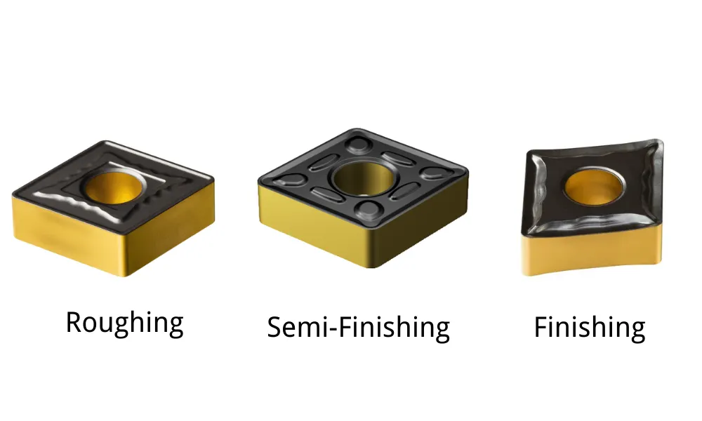
Son İşleme, Orta ve Kaba İşleme Talaş Kırıcıları
Tornalama geometrilerinin çoğu, üç geniş uygulama grubuna ayrılabilir.
| Özellik | Son işlem geometrisi | Orta geometri | Kaba işleme geometrisi |
| Tipik yem | Düşük | Orta | Yüksek |
| Tipik kesme derinliği | Küçük | Orta ve geniş kapsamlı | Büyük |
| Tırmık eğilimi | Daha olumlu | Orta derecede olumlu veya dengeli | Nötr ila az olumlu |
| En son teknoloji | Sharp | Dengeli | Güçlendirilmiş |
| Kenar bileme | Küçük | Orta | Daha büyük veya daha koruyucu |
| Kesme kuvvetleri | Daha düşük | Orta düzeyde | Daha yüksek |
| Yüzey kalitesi potansiyeli | Yüksek | İyi | İkinci öncelik |
| Kesintiye uğramış kesim özelliği | Sınırlı | Orta düzeyde | Daha yüksek |
| En uygun kullanım | Hafif son işlem ve ince parçalar | Genel amaçlı üretim | Yoğun malzeme kaldırma |
Sandvik, son işlem geometrilerini düşük ilerlemeler ve küçük kesme derinlikleri için keskin kenarlı çözümler olarak, orta geometrileri çok yönlü bir seçenek olarak ve kaba işleme geometrilerini ise daha yüksek ilerlemeler ve daha ağır kesimler için tasarlanmış daha dayanıklı paketler olarak tanımlamaktadır.
Son İşlem Çip Kırıcıları
Son işlem talaş kırıcı, ince talaşla çalışmak üzere tasarlanmıştır.
Tipik özellikleri şunlardır:
- kesme kenarına yakın dar talaş kontrol özellikleri;
- pozitif eğim açısı;
- keskin kesme kenarı;
- küçük kenar bileme taşı;
- düşük kesme kuvvetleri.
Genellikle şu amaçlarla tercih edilir:
- küçük kesme derinlikleri;
- düşük beslemeler;
- ince cidarlı parçalar;
- düşük rijitlikli kurulumlar;
- hassas son işlem;
- iyi yüzey kalitesi gerektiren uygulamalar.
Son işlem geometrisi, normalde ağır kaba işleme veya zorlu kesintili kesme işlemleri için kullanılmamalıdır. Keskin kenarı, dayanması için tasarlanmadığı yükler altında ufalanabilir veya kırılabilir.
Orta Boy Talaş Kırıcılar
Orta boy bir talaş kırıcı, genel amaçlı kullanımda en geniş uygulama yelpazesini sunar.
Aşağıdaki durumlarda genellikle ilk olarak bu geometri test edilir:
- işlem istikrarlıdır;
- besleme ve kesme derinliği orta düzeydedir;
- hem yonga kontrolü hem de kenar mukavemeti önemlidir;
- parça birden fazla kesme derinliği içermektedir;
- Tek bir takma parçası, yarı bitirme ve genel tornalama işlemlerini gerçekleştirmelidir.
Orta geometri, her iş için otomatik olarak en iyi seçenek değildir. Minimum ilerleme hızı veya kesme derinliğinin altında kullanıldığında yine de uzun talaşlar üretebilir.
Kaba İşleme Talaş Kırıcıları
Bir kaba işleme talaş kırıcı şu amaçlarla tasarlanmıştır:
- büyük kesme derinlikleri;
- daha yüksek ilerleme hızları;
- yoğun malzeme kaldırma;
- dövme veya döküm yüzeyler;
- kesintili kesme;
- yüksek ve son derece zorlu yükler.
Genellikle daha geniş bir çip alanı ile güçlendirilmiş kenar, daha geniş temas yüzeyi veya daha ağır bileme taşını bir arada barındırır.
Son derece hafif bir son işlem kesimi için kaba işleme geometrisinin kullanılması şu sorunlara yol açabilir:
- temiz kesme yerine sürtme;
- artmış kesme kuvvetleri;
- yüzey kalitesinin düşük olması;
- aşırı sıcak;
- Talaş, oluğa tam olarak oturamayacak kadar ince olduğu için talaş kontrolü yetersiz kalır.
Hangi Durumlarda Düz Üstlü veya Zayıf Talaş Kırıcı Daha Uygun Olabilir?
Güçlü bir talaş kırıcı her zaman gerekli değildir.
Doğal Olarak Kısa Tırnak Oluşumuna Neden Olan Malzemeler
Gri dökme demir ve bazı kolay işlenebilir bakır alaşımları doğal olarak kısa talaşlar üretir. Bu uygulamalarda talaş kırma, aşağıdakilerden daha az önemli olabilir:
- kenar mukavemeti;
- aşınma direnci;
- kullanılabilir kesme kenarlarının sayısı;
- kenar başına maliyet.
Bu nedenle, düz üstlü veya hafif şekillendirilmiş bir ek parça uygun olabilir.
Ağır Kesintili Kesme
Derin oluklar, çapraz delikler, pullar ve kesintili yüzeyler, kenarı darbelere maruz bırakır.
Karmaşık ve derin bir oluk, kesme kenarını destekleyen malzeme miktarını azaltabilir. Daha sağlam bir düz tepe veya güçlendirilmiş geometri, kenar kırılma riskini azaltabilir.
Kesme Kuvveti Çok Düşük Olan Uygulamalar
İşleme sırasında:
- ince duvarlar;
- küçük çaplı bileşenler;
- ince yüz hatları;
- kararsız kurulumlar;
- demir dışı malzemeler;
Parçanın sapmasını ve titreşimini en aza indirmek için, nispeten zayıf talaş tutma özelliğine sahip keskin ve açık bir geometri tercih edilebilir.
Yüzey Kalitesi Açısından Önemli İşlemler
İş parçasına doğru şiddetle kıvrılan bir talaş, yeni işlenmiş yüzeyi çizebilir.
Daha az kısıtlayıcı bir geometri, daha uygun talaş yönü veya ayarlanmış soğutma sıvısı akışı, talaş biraz daha uzun olsa bile daha pürüzsüz bir yüzey elde edilmesini sağlayabilir.
Agresif bir talaş kırıcının bulunmaması, her zaman bir tasarım zayıflığı anlamına gelmez. Bu, belirli bir işlem için doğru mühendislik tercihi olabilir.
[İç bağlantı: Pozitif ve Negatif Tırmık Uçlar]
Kesme Koşullarının Talaş Kırıcının Performansını Nasıl Etkilediği
Bir talaş kırıcı, kesme verilerinden ayrı olarak değerlendirilemez.
Besleme Oranı
İlerleme hızı, talaş kalınlığı üzerinde en büyük etkiye sahip faktörlerden biridir.
Yem miktarı çok az:
- çip incedir;
- çip, yeterince kıvrılmadan oluğun üzerinden akabilir;
- sürtünme ve kenar kalıntıları oluşabilir;
- uzun, ipliksi cipsler oluşabilir.
Yem miktarı çok fazla:
- son derece yüksek yük artışları;
- çipler aşırı derecede kısa veya şiddetli hale gelebilir;
- ek parça ufalanabilir;
- Makinenin gücü ve kararlılığı sınırlayıcı faktörler haline gelebilir.
Kesim Derinliği
Kesme derinliği, kesici kenarın ve talaş kırıcının geometrisinin ne kadarının devreye girdiğini belirler.
Kesme derinliği çok az:
- çentik esas olarak burun yarıçapı çevresinde oluşur;
- çip, hedeflenen kesici özelliğine ulaşamayabilir;
- Çip kontrolü tutarsız hale gelir.
Kesme derinliği çok fazla:
- çip, devre kesicinin kapasitesini aşabilir;
- kenar yükü artar;
- çipin tahliyesi kısıtlanabilir;
- Kesim işlemi, kenarın desteklenmeyen bir bölümünü kullanabilir.
Kesim Hızı
Kesme hızı şunları etkiler:
- sıcaklık;
- yükseltilmiş kenar;
- malzeme akışı;
- alet aşınması;
- çipin sünekliği.
Bu etki, malzemeye göre değişir.
Bazı sünek malzemelerde, hızın artırılması kenar birikimini azaltabilir, ancak sıcak talaşın kırılmasını zorlaştırabilir. Diğer uygulamalarda ise çok düşük bir hız, yapışmayı ve dengesiz talaş oluşumunu teşvik eder.
Bu nedenle hız, her türlü yonga sorununa yönelik ilk genel düzeltme yöntemi olarak kullanılmak yerine, yonga üreticisinin önerdiği aralık içinde ayarlanmalıdır.
Soğutma sıvısı
Soğutma sıvısı şunları etkileyebilir:
- çip yönü;
- tırmık yüzeyindeki sürtünme;
- çip sıcaklığı;
- yükseltilmiş kenar;
- çip tahliyesi;
- termal şok.
Yüksek basınçlı ve hassas bir şekilde yönlendirilmiş soğutma sıvısı, uzun talaşların uzaklaştırılmasının zor olduğu durumlarda özellikle yararlıdır. Bu yöntem, önerilen ilerleme hızı ve kesme derinliği aralığının tamamen dışında kalan bir talaş kırıcıyı telafi etmek için kullanılmamalıdır.
Giriş Açısı
Giriş açısı, talaş kalınlığını ve genişliğini değiştirir.
Daha küçük bir giriş açısı, aynı ilerleme hızında genellikle daha ince ve daha geniş bir talaş oluştururken, daha büyük bir giriş açısı ise daha kalın ve daha dar bir talaş oluşturur. Bu durum, işleme işlemini talaş kırıcının etkili menzilinin içine veya dışına taşıyabilir.
İş Parçası Malzemesine Göre Talaş Kırıcı Seçimi
ISO P: Çelik
Çelik, talaş kırıcı seçiminde genellikle en öngörülebilir malzeme grubudur; ancak davranışları karbon içeriği, alaşım bileşimi ve sertliğe göre önemli ölçüde değişiklik gösterir.
Düşük Karbonlu Çelik
Düşük karbonlu çelik sünek bir malzemedir ve genellikle uzun talaşlar ve birikmiş kenar oluşumuna neden olur.
Yararlı geometrik özellikler şunlardır:
- pozitif eğim;
- keskin kesme etkisi;
- düşük ila orta hızda ilerlemede güvenilir yonga kıvrılması;
- yapışmayı önleyici kaplama veya yüzey işleme.
Kesme derinliği burun yarıçapına göre son derece küçükse, talaş talaş kırıcıya tam olarak oturmayabilir.
Orta Karbonlu ve Alaşımlı Çelik
Bu malzemeler genellikle orta boy talaş kırıcılar için geniş bir çalışma aralığı sağlar.
Geometriyi aşağıdakilere göre seçin:
- son işlem veya kaba işleme;
- sürekli veya kesintili kesim;
- dövme veya işlenmiş yüzey;
- gerçek ilerleme hızı ve kesme derinliği.
Yüksek Alaşımlı veya Daha Sert Çelik
Daha yüksek sıcaklık ve kesme kuvvetleri, pratik talaş kontrol aralığını daraltabilir.
Talaş kırıcı şekli uygun görünse bile, daha sağlam bir kesici kenar ve ısıya dayanıklı bir kalite gerekebilir.
ISO M: Paslanmaz Çelik
Ostenitik paslanmaz çelik, uzun ve işlenmesi zor talaşların en yaygın kaynaklarından biridir.
Ayrıca şu eğilimleri de gösterir:
- sertleşme;
- dolgulu kenar;
- yüksek ısı üretir;
- çentik aşınmasına neden olur;
- takıma veya iş parçasına çarpan sert talaşlar oluşturur.
Önerilen başlangıç özellikleri şunlardır:
- pozitif eğim;
- keskin kesme kenarı;
- malzemeye özel talaş kırıcı;
- sabit kesme derinliği;
- kırıcıyı çalıştırmak için yeterli besleme;
- soğutma sıvısının doğru şekilde yönlendirilmesi.
İşsertleşmiş bir yüzey üzerinde, kesme derinliği aşırı derecede küçük olacak şekilde tekrar tekrar sürtünmekten kaçının.
Dubleks paslanmaz çelik, birçok östenitik çelik türüne kıyasla daha güçlü ve daha sert talaşlar ile daha yüksek kesme kuvvetleri oluşturur. Kenar mukavemeti ve işlem istikrarı daha da önem kazanır.
ISO K: Dökme Demir
Gri dökme demir genellikle kısa, kendiliğinden kırılan talaşlar oluşturur. Bu nedenle talaş kontrolü, aşınma, toz ve kenar aşınmasına kıyasla genellikle daha az zordur.
Aşağıdaki durumlarda güçlü veya düz üst geometri seçilebilir:
- kesik sabit;
- malzeme doğal olarak parçalanır;
- Maksimum kesme kenarı mukavemeti gereklidir.
Sünek döküm ve sıkıştırılmış grafitli döküm, gri dökümle tam olarak aynı davranış göstermez. Bu malzemeler daha uzun talaşlar, daha yüksek kuvvetler ve daha fazla ısı üretebileceğinden, özel bir geometri ve kalite sınıfı seçilmelidir.
ISO N: Alüminyum ve Demir Dışı Malzemeler
Alüminyum, düşük kesme kuvveti gerektirir ve malzeme yapışmasına karşı yüksek direnç gösterir.
Tipik geometrik özellikler şunlardır:
- son derece yüksek komisyon oranı;
- çok keskin bir kesici kenar;
- cilalı üst yüzey;
- geniş yonga alanı;
- minimal kenar bileme;
- Uygulamaya bağlı olarak kaplamasız karbür, DLC kaplamalı karbür veya PCD.
Saf ve yumuşak alüminyum, çok uzun ve yapışkan talaşlar oluşturabilir. Döküm alüminyum alaşımları genellikle talaş kontrolünü kolaylaştırır; ancak yüksek silikonlu alüminyum oldukça aşındırıcıdır ve PCD takımlarının kullanılmasını gerektirebilir.
Pirinç ve bazı bronz alaşımları daha kısa talaşlar oluşturur ve daha az agresif talaş kırma gerektirebilir.
Örneğin, Iscar’ın alüminyum kesimine yönelik geometrilerinde, yapışmayı ve kesme kuvvetlerini azaltmak amacıyla yüksek pozitif eğim açısı, taşlanmış ve parlatılmış eğim yüzeyi ile keskin bir kesme kenarı kullanılmaktadır.
[İç bağlantı: Alüminyum için CCGT Ek Parçaları]
[İç bağlantı: Alüminyum Son İşlem için DCGT Ek Parçaları]
ISO S: Titanyum ve Isıya Dayanıklı Süper Alaşımlar
Titanyum, nikel bazlı süper alaşımlar ve kobalt bazlı alaşımlar, yüksek sıcaklıklarda önemli ölçüde mukavemetlerini korurlar.
Sık karşılaşılan zorluklar arasında şunlar yer almaktadır:
- yoğun kesme ısısı;
- çentik aşınması;
- yükseltilmiş kenar;
- yüksek dinamik kesme kuvvetleri;
- uzun veya parçalı, kontrol edilmesi zor talaşlar;
- ani kenar kırılması.
Uygun çalıştırma özellikleri genellikle şunları içerir:
- pozitif kesme geometrisi;
- keskin ancak yeterince desteklenmiş kenar;
- sert karbür alt tabaka;
- PVD uygun olduğu durumlarda kaplama;
- kontrollü kesme hızı;
- yüksek basınçlı soğutma sıvısı;
- sürekli katılım.
Bu malzemeler için talaş kırıcı, kenar hazırlığı, kesici uç kalitesi ve soğutma sıvısı stratejisinden bağımsız olarak seçilmemelidir.
ISO H: Sertleştirilmiş Malzemeler
Sertleştirilmiş çelikler genellikle CBN, seramik veya özel aletlerle son tornalama işlemine tabi tutulur karbür uçlar.
Talaş kontrolü, malzemenin genellikle kısa veya parçalı talaşlar üretmesi nedeniyle nispeten kolay olabilir. Daha önemli hususlar arasında şunlar sayılabilir:
- son derece yüksek mukavemet;
- yan kısım aşınması;
- krater aşınması;
- termal kararlılık;
- boyutsal tutarlılık;
- yüzey bütünlüğü.
Bazı CBN kesici uçlar, hafif son işlem sırasında talaş yönünü iyileştirmek ve kesme kuvvetlerini azaltmak amacıyla lazerle üretilmiş veya kalıplanmış talaş kırıcı özelliklere sahiptir. Geometri, kırılgan kesici takım malzemesi için özel olarak tasarlanmalıdır.
[İç bağlantı: Sert Tornalama İşlemlerinde Neden Katı CBN Uçları Kullanılmalıdır?]
Yetersiz Çip Kontrolü Sorunlarının Giderilmesi
Kesici ucu değiştirmeden önce, mevcut kesme koşullarının üreticinin talaş kırıcı tablosunda belirtilen aralıkta olup olmadığını kontrol edin.
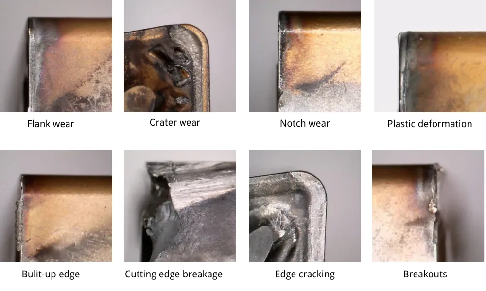
| Belirti | Olası nedenler | Düzeltici önlemler |
| Uzun, kesintisiz talaşlar | Besleme çok düşük; kesme derinliği çok az; kırıcı çok açık; talaş kırıcı devrede değil | Önerilen aralık dahilinde ilerleme hızını artırın; mümkünse kesme derinliğini artırın; düşük ilerleme hızında daha etkili talaş kontrolü sağlayan bir geometri seçin |
| Aletin çevresinde kuş yuvaları | Talaş yönü uygun değil; uzun ve esnek talaşlar; soğutma sıvısı yönü yetersiz | Talaş yönünü iyileştirin; alet içinden geçen veya yüksek basınçlı soğutma sıvısı kullanın; kırıcı geometrisini değiştirin; tutucunun giriş açısını gözden geçirin |
| Son derece kısa ve sert yongalar | Besleme hızı çok yüksek; talaş tutma kuvveti çok fazla; geometri çok agresif | İlerleme miktarını azaltın; daha açık veya pozitif bir geometri seçin; kesici kenardaki hasarı kontrol edin |
| Cipsler, cilalanmış yüzeyi çiziyor | Talaşlar bileşene doğru kıvrılıyor; talaş tahliyesi yetersiz; soğutma sıvısı talaşları yanlış yönde itiyor | Takımın yönünü değiştirin; soğutma sıvısının yönünü ayarlayın; daha az kısıtlayıcı bir geometri seçin; takımın yaklaşma şeklini değiştirin |
| Kesici kenara talaşları yerleştirin | Geometri çok keskin; kesim kesintiye uğramış; ilerleme veya kesme derinliği aşırı; kurulum dengesiz | Daha sağlam bir geometri ve daha dayanıklı bir malzeme sınıfı seçin; yükü azaltın; çıkıntıyı kısaltın; iş parçasının sabitlenmesini iyileştirin |
| Yükseltilmiş kenar | Hız çok düşük; geometri çok köşeli; uygun olmayan kaplama; yetersiz yağlama | Daha keskin bir pozitif geometri kullanın; hızı önerilen sınırlar içinde ayarlayın; soğutma sıvısını veya yağlamayı iyileştirin; yapışmayı önleyici bir malzeme sınıfı kullanın |
| Kenarları sağlam olmasına rağmen yüzey kalitesi düşük | Hafif kesimde kullanılan kaba işleme geometrisi; sürtünme; talaşın yeniden kesilmesi; titreşim | Son işlem geometrisini kullanın; minimum ilerleme hızını sağlayın; talaş tahliyesini iyileştirin; uç yarıçapını ve rijitliği kontrol edin |
| Kesici uç aşındıkça yonga kontrolü bozulur | Krater aşınması, tırmık geometrisini değiştirir; kenar yuvarlaklaşır; kaplama bozulur | Ek parçayı daha erken yerleştirin; eğimi ve hızı kontrol edin; soğutma sıvısı beslemesini inceleyin |
| Talaşlar kenara çarparak hasara yol açar | Talaş yönü yanlış; kesici alet çok dar; iş parçasıyla temas sırasında aşırı kesme | Talaş kırıcıyı değiştirin; tutucu açısını veya soğutma sıvısını ayarlayın; aşırı kıvrılmayı azaltın |
| Parça çevresinde yonga şekli değişir | Değişken kesme derinliği; değişen giriş açısı; kesintili şekiller; malzeme farklılıkları | Daha geniş aralıklı bir geometri kullanın; kesme derinliğini sabitleyin; gerektiğinde ayrı geçişler programlayın |
| Yüksek kesme kuvvetleri veya iş mili yükü | Geometri çok kaba; kesici yüzey veya bileme yüzeyi çok geniş; ilerleme veya kesme derinliği aşırı | Daha uygun bir geometri seçin; kesme verilerini azaltın; merkez yüksekliğini ve tutucunun hizalamasını kontrol edin |
| Kesici uçların değiştirilmesinden sonra gıcırtı sesi duyulur | Yeni geometride kuvvetler daha yüksek; burun yarıçapı çok büyük; desteklenmeyen kenar veya ayar | Daha az kuvvet gerektiren bir geometri kullanın; çıkıntıyı azaltın; sıkıştırmayı iyileştirin; burun yarıçapını ve kesme yönünü gözden geçirin |
Önerilen Sorun Giderme Sırası
Çipler düzgün bir şekilde kırılmadığında, değişkenleri şu sırayla kontrol edin:
- Takma parçası ve talaş kırıcının tam tanımını doğrulayın.
- İlerleme hızı ve kesme derinliğinin katalogda belirtilen aralık içinde olup olmadığını kontrol edin.
- İş parçasının malzemesini ve sertliğini kontrol edin.
- Kesici kenarda aşınma veya birikmiş malzeme olup olmadığını kontrol edin.
- Tutucunun yönünü, merkez yüksekliğini ve giriş açısını kontrol edin.
- Soğutma sıvısı basıncını ve akış yönünü kontrol edin.
- Makine ve iş parçası tutucusunun stabilitesini kontrol edin.
- Yukarıdaki koşulları iyice anladıktan sonra yonga kırıcı geometrisini değiştirin.
- Aşınma, ısı veya kenar dayanıklılığı gerçek sınırlayıcı faktör ise, kesici uç kalitesini değiştirin.
- Gelecekteki üretim için başarılı olan parametreleri belgelendirin.
Frezleme uçlarında da talaş kırıcılar kullanılır mı?
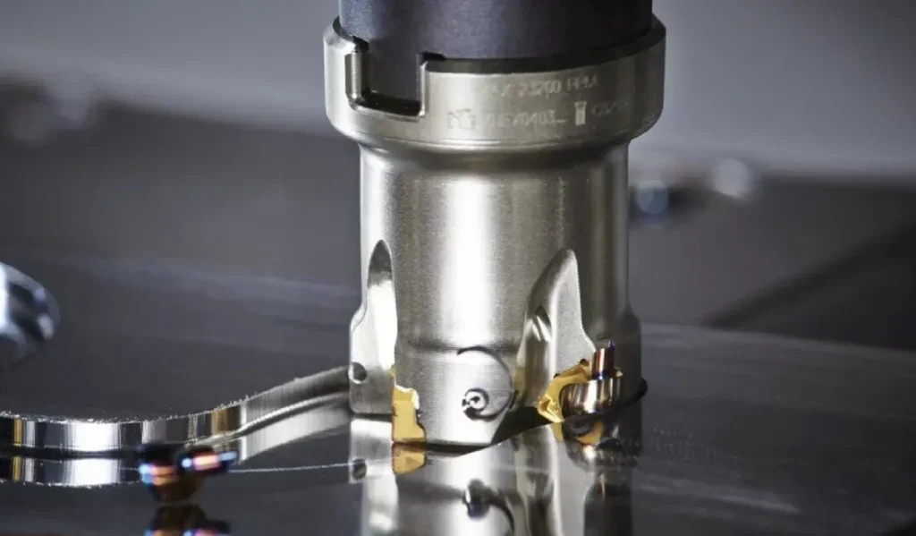
Evet, ancak freze üreticileri genellikle daha geniş kapsamlı olan terimi kullanırlar geometriyi ekle çip kırıcıyı ayrı bir özellik olarak ele almak yerine.
Tornalama işlemi sırasında kesici kenar sürekli olarak malzemeyle temas halinde kalabileceğinden, talaşın kesintisiz bir şekilde uzaklaştırılmasını sağlamak en önemli husustur.
Frezeleme işleminde:
- kesim kesintiye uğrar;
- diş içeri girip çıkarken çip kalınlığı değişir;
- kesici kenar iş parçasından ayrıldığında talaşlar genellikle kendiliğinden ayrılır;
- Talaş tahliyesi, kesme kuvveti ve kenar mukavemeti, kesintisiz talaşın kırılmasından daha önemli olabilir.
Bir freze ucu üst geometrisinin etkisi hâlâ devam etmektedir:
- etkili eğim açısı;
- kesme kuvveti;
- çip akışı;
- yükseltilmiş kenara karşı direnç;
- kenar mukavemeti;
- yüzey kalitesi.
Frezeleme geometrileri genellikle şu kategorilere ayrılır:
- alüminyum veya demir dışı metal geometrisi;
- ışık kesme geometrisi;
- genel amaçlı geometri;
- ağır hizmet tipi geometri.
Bir freze uçları geometri, kullanım:
- diş başına besleme,
fz; - eksenel kesme derinliği,
ap; - kesme genişliğinin yarıçapı,
ae; - kesicinin giriş açısı;
- kesici çapı;
- birbirine geçen diş sayısı;
- makinenin kararlılığı.
Bir torna talaş kırıcı tablosunu doğrudan bir freze uçları.
[İç bağlantı: Doğru Freze Uçları Nasıl Seçilir?]
[İç bağlantı: Uygulamaya Göre Freze Uçları]
Doğru Yonga Kırıcıyı Seçmek İçin Gerekli Bilgiler
Bir tedarikçiden bir kesici uç önermesini isterken, sadece temel ISO kodunu belirtmekle yetinmeyin.
Gönder:
- mevcut ek tanımını tamamlayın;
- biliniyorsa üreticiyi girin;
- takım tutucu tanımı;
- dış, iç, yüzey işleme, profilleme veya oluk açma işlemi;
- iş parçası malzemesi ve kesin kalite sınıfı;
- iş parçasının sertliği;
- kesme derinliği;
- devir başına besleme;
- kesme hızı;
- sürekli veya kesintili kesme;
- kuru, sel tipi veya yüksek basınçlı soğutma sıvısı;
- mevcut yonga şekli;
- mevcut aşınma veya arıza türü;
- gerekli yüzey kalitesi;
- ek parçanın, tutucunun, iş parçasının ve talaşların fotoğrafları;
- gerekli miktar.
Çiplerin bir fotoğrafı, “ek parça çalışmıyor” gibi bir açıklamadan genellikle daha yararlıdır.”
Sıkça Sorulan Sorular
Çip kırıcı, sadece kesici uç üzerindeki bir oluk mu?
Hayır. Pratik kesici uç mühendisliğinde, talaş kırıcı, eğim yüzü, ara yüzey, pah ve kenar hazırlığını içeren eksiksiz bir kesici kenar geometrisinin bir parçasıdır.
Tüm karbür uçlarda talaş kırıcı bulunur mu?
Hayır. Bazı kesici uçların eğim yüzeyleri düzdür ya da talaş oluşturma özellikleri oldukça zayıftır. Bunlar, doğal olarak kısa talaş oluşturan malzemeler, ağır kesintili kesme işlemleri veya kenar mukavemetine öncelik verilen uygulamalar için uygun olabilir.
Talaş kırıcı kodları standartlaştırılmış mıdır?
Hayır. Uç tanımlamasındaki ISO kısmı, şekil, boşluk, tolerans, boyut ve uç yarıçapı gibi özellikleri standartlaştırır. Talaş kırıcı sonekleri ve geometri adları genellikle üreticiye özeldir.
Son işlem için hangi talaş kırıcı kullanılmalıdır?
Gerçek iş parçası malzemesi ile hedeflenen ilerleme hızı ve kesme derinliği için tasarlanmış bir son işlem geometrisi kullanın. Bu geometri, kaba işleme geometrisine kıyasla genellikle daha keskin bir kenara ve daha düşük kesme kuvvetlerine sahiptir.
Genel tornalama işleri için en uygun talaş kırıcı hangisidir?
Orta veya genel amaçlı bir geometri, genellikle kararlı ve orta yükte tornalama işlemleri için ilk tercih edilen seçenektir. Ancak, katalogdaki aralığı, gerçek ilerleme hızı ve kesme derinliği ile uyumlu olmalıdır.
Neden kesici uçum uzun, ipliksi talaşlar üretiyor?
Sık görülen nedenler arasında, talaş kırıcının minimum aralığının altındaki ilerleme hızı, çok küçük kesme derinliği, aşırı açık geometri, yanlış giriş açısı veya uygun olmayan soğutma sıvısı yönü sayılabilir.
Besleme hızının artırılması talaş kırılmasını iyileştirebilir mi?
Evet. Daha yüksek bir ilerleme hızı, talaş kırıcıya daha etkili bir şekilde temas edebilecek daha kalın bir talaş oluşturur. İlerleme hızı, kesici uç, kalite sınıfı, makine ve bileşen sınırları içinde kalmalıdır.
Çok kısa fişler her zaman daha mı iyidir?
Hayır. Aşırı kısa veya parçalanmış talaşlar, talaşın aşırı kısıtlandığını ve kesici kenarda yüksek yük oluştuğunu gösterebilir.
Aynı kesici uç şekli için farklı talaş kırıcılar kullanılabilir mi?
Evet. CNMG, WNMG, CCMT, DCMT ve diğer uç aileleri, farklı malzemeler ve işleme aralıkları için çeşitli talaş kırıcılarla sunulmaktadır.
Talaş kırıcı, yüzey kalitesini etkiler mi?
Evet. Kesme kuvveti, talaş yönü, kenar keskinliği ve talaşın işlenmiş yüzeye temas edip etmemesi üzerinde etkili olur. Bununla birlikte, uç yarıçapı, ilerleme hızı, eksantriklik, titreşim ve kesici uç aşınması da yüzey kalitesini etkiler.
Önce talaş kırıcıyı mı yoksa kesici uç kalitesini mi değiştirmeliyim?
Ana sorun talaş oluşumu, kesme kuvveti veya geometri aralığı ise talaş kırıcıyı değiştirin. Ana sorun aşınma direnci, ısı direnci veya tokluk ise kaliteyi değiştirin. Çoğu durumda, her ikisi de birbiriyle uyumlu bir kombinasyon olarak seçilmelidir.
Frezleme uçlarında talaş kırıcılar gerekli midir?
Freze uçları, birçok ortak işlevi yerine getiren çeşitli geometrilere sahiptir. Bununla birlikte, bu uçlar, diş başına ilerleme, eksenel derinlik ve radyal temas değerleri dikkate alınarak frezelemeye özgü tablolardan seçilmelidir.
Nihai Seçim Kontrol Listesi
Bir ek sipariş etmeden önce şunları teyit edin:
- Geometri, iş parçası malzemesine göre tasarlanmıştır;
- geometri, ince işleme, orta kesme veya kaba işleme ile uyumludur;
- besleme ve kesme derinliği, talaş kontrol haritasının sınırları içinde kalır;
- kenar hazırlığı kesim için yeterince sağlamdır;
- ek parçasının kalitesi, ısı, aşınma ve stabilite gereksinimlerini karşılamaktadır;
- tutucu açısı ve burun yarıçapı, istenen talaş şeklinin elde edilmesini sağlar;
- soğutma sıvısı kesme bölgesine ulaşabilir;
- Ek son eki, ilgili üretici kataloğunda kontrol edilmiştir.
Amaç, mümkün olan en kısa çipi üretmek değildir.
Buradaki amaç, aşağıdakiler arasında istikrarlı bir denge sağlamaktır:
- kontrollü yonga oluşumu;
- kontrol edilebilir kesme kuvvetleri;
- yeterli uç mukavemeti;
- kabul edilebilir takım ömrü;
- güvenilir yüzey kalitesi;
- talaşın güvenli bir şekilde uzaklaştırılması.
Mevcut bir tornalama işlemine uygun talaş kırıcı seçmek için yardıma mı ihtiyacınız var? Uyumluluk ve geometri incelemesi için eksiksiz kesici uç kodunu, takım tutucu modelini, iş parçası malzemesini, kesme parametrelerini ve talaşların bir fotoğrafını gönderin.