Струголом часто называют канавку, которая разбивает длинные металлические стружки на более короткие кусочки. Это описание верно, но неполно.
При выборе режущей пластины на практике стружколок целесообразно рассматривать как полностью инновационная геометрия. Как правило, он сочетает в себе канавку на верхней поверхности, угол наклона, фаску или скос, хонингованную кромку и другие элементы, расположенные вокруг режущей кромки.
Эти функции взаимодействуют друг с другом, обеспечивая управление тремя аспектами:
- Формирование и удаление стружки;
- Силы резания и тепловыделение;
- Непревзойденная прочность и устойчивость к сколам.
Таким образом, лучшим стружколомом не всегда является та геометрия, которая обеспечивает получение стружки минимальной длины. Лучшим является та геометрия, которая позволяет получать стружку, удобную для удаления, при этом обеспечивая приемлемые режущие усилия, качество поверхности и срок службы инструмента.
Краткий ответ: Выберите стружколок с учетом вида обработки, материала заготовки, скорости подачи и глубины резания. Затем убедитесь, что форма кромки и марка пластины обеспечивают достаточную прочность для стабильности резания.
Данное руководство посвящено в первую очередь сменные токарные пластины. Те же основные принципы применимы и к режущим пластинам для рифления, отсечки и фрезерования, хотя условия резания и таблицы выбора производителей отличаются.
Что такое вставной отломщик стружки?
В самом узком смысле стружколок представляет собой канавку, ступеньку или выступ, образованный на передней поверхности режущей вставки. Его назначение заключается в том, чтобы изменить направление движения стружки и закрутить её до тех пор, пока она не сломается или не будет безопасно удалена из зоны резания.
Однако современные производители вставок Как правило, отломщик стружки проектируется в рамках комплексной геометрии.
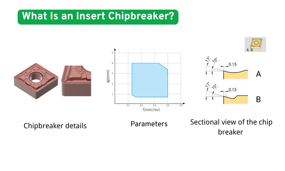
Основные элементы геометрии стругового резака
| Элемент геометрии | Функция |
|---|---|
| Ширина паза выключателя | Определяет, на какое расстояние чип пролетит, прежде чем его заставит закрутиться |
| Глубина канавки или высота стенки | Определяет степень перенаправления чипа |
| Угол наклона граблей | Влияет на поток стружки, режущую силу и тепловыделение |
| Передовая территория | Обеспечивает опору непосредственно за режущей кромкой |
| Угловой выступ или Т-образный выступ | Укрепляет кромку при выполнении более тяжелых или прерывистых пропилов |
| Брусок для заточки кромок | Снижает образование микротрещин за счет скругления и укрепления кромки |
| Местные выпуклости или впадины | Направлять, разделять или скручивать стружку в определенных зонах резания |
| Полированная рабочая поверхность граблей | Снижает адгезию к алюминию и другим цветным металлам |
Эти характеристики нельзя рассматривать изолированно. Например, значительный положительный угол наклона может снизить режущие усилия, но при этом, как правило, уменьшается площадь материала, поддерживающего режущую кромку. Более широкая затылочная поверхность или более интенсивная заточка кромки повышают прочность кромки, но также могут увеличить режущее давление.
Таким образом, выбор отломщика — это поиск оптимального баланса:
- управление микросхемой;
- стойкость к порезам;
- прочность кромки;
- отделка поверхности;
- стабильность процесса.
Почему управление микросхемами имеет значение
Ненадлежащий контроль за стружкой может привести к проблемам, выходящим далеко за рамки простого беспорядка в корпусе станка.
Длинные непрерывные стружки могут:
- обхватить заготовку, вставку или держатель инструмента;
- поцарапать готовую поверхность;
- перекрыть поток охлаждающей жидкости;
- заклинить конвейер для чипов;
- мешать автоматической смене инструмента;
- повредить шланги, датчики или расположенные поблизости инструменты;
- заставить оператора остановить станок;
- приводят к возникновению сложных и опасных условий управления автомобилем.
При автоматизированном токарном обрабатывании, обработке без участия оператора и крупносерийном производстве даже один сбой в системе контроля стружки может привести к остановке в остальном стабильного технологического процесса.
Подходящий срыватель стружки способствует скручиванию и направлению стружки таким образом, чтобы она могла покинуть зону резания, не мешая ни инструменту, ни детали. Компания Sandvik выделяет геометрию срывателя стружки, подачу, глубину резания и радиус носка в качестве основных факторов, влияющих на контроль стружки при токарной обработке.
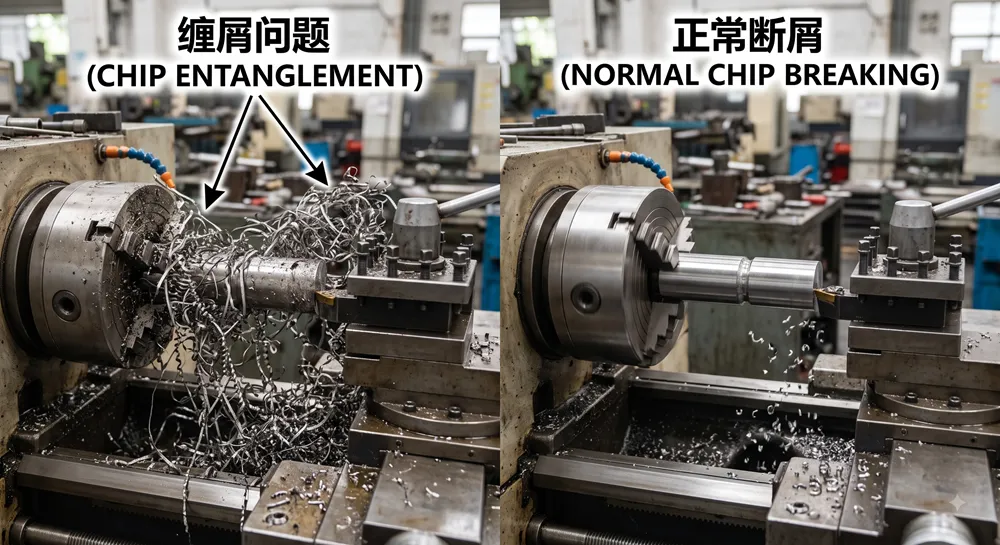
Спиральный резец выполняет три основные функции
1. Управление микросхемой
Геометрия изгибает, скручивает и направляет стружку таким образом, чтобы она ломалась или безопасно удалялась.
2. Регулировка режущих усилий
Геометрия передней поверхности и кромки режущего инструмента определяет, насколько легко материал заготовки перемещается по пластине. Более острая, положительная геометрия обычно обеспечивает резку с меньшими усилиями, тогда как более прочная геометрия, как правило, требует приложения большего усилия.
3. Защита режущей кромки
Зубья, фаска и кромка хона обеспечивают механическую опору. Эти особенности особенно важны при черновой обработке, прерывистом резании, удалении окалины и при нестабильной обработке.
Поэтому при выборе отломщика стружки ни в коем случае нельзя руководствоваться только следующим вопросом:
“Не повредит ли такая геометрия микросхему?”
Лучше задать следующий вопрос:
“Позволит ли это обеспечить контроль над чипом при одновременном сохранении достаточной прочности кромок, ресурса инструмента и качества поверхности?”
Как стругорез разрубает стружку?
Образование стружки начинается в тот момент, когда режущая кромка срезает материал с заготовки. Вновь образовавшаяся стружка перемещается по передней поверхности пластины.
Струголомщик изменяет направление и кривизну стружки на четырёх основных этапах.
1. Формирование чипа
Материал срезается с заготовки и начинает течь по передней поверхности режущего инструмента.
2. Чип-керлинг
Канавка, стенка или рельефная геометрия заставляют стружку изгибаться с меньшим радиусом.
3. Накопление напряжений
По мере скручивания заготовки по всей её толщине возникает изгибающая деформация.
4. Отделение чипов
Когда напряжение достигает достаточно высокого значения или когда загнутая стружка соприкасается с другой поверхностью, стружка ломается.
Распространенные способы отвода стружки
Чип может сломаться по-разному.
Самоторможение
Стружка ломается из-за собственной кривизны и изгибной деформации.
Упор против вставки
Скрученная стружка соприкасается со стенкой стружколома или другой частью пластины и ломается.
Упор против заготовки
Стружка закручивается обратно к поверхности заготовки и отламывается при соприкосновении.
Выбор наиболее подходящего режима зависит от вида обработки. Контакт стружки с заготовкой может быть допустим при некоторых операциях черновой обработки, но может привести к повреждению поверхности при чистовой обработке.
Как выглядит хороший чип?
Самый короткий фишка — не всегда лучшая фишка.
Хороший чип, как правило, — это:
- достаточно короткий, чтобы не обмотаться вокруг инструмента или детали;
- достаточно длинные, чтобы не превратиться в острые, раскаленные осколки;
- облегчает отвод охлаждающей жидкости и удаление стружки;
- направленное в сторону, противоположную обработанной поверхности;
- одинаковый на всем протяжении среза.
К числу общепринятых форм относятся:
- компактные C-образные стружки;
- короткие спиралевидные стружки;
- многовитковые спиральные стружки, которые отламываются естественным образом.
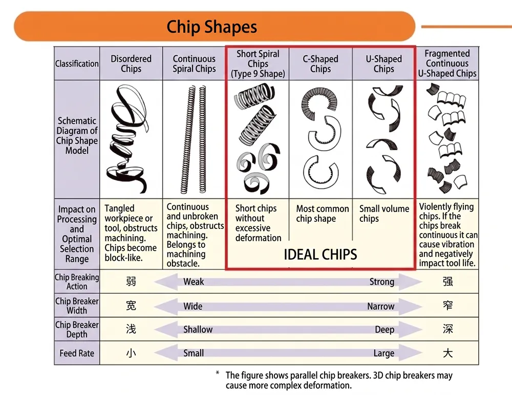
Внешний вид чипа как диагностический инструмент
| Внешний вид микросхемы | Вероятная интерпретация |
| Длинные непрерывные строки | Стружка слишком тонкая, прерыватель не сработал или геометрия слишком открытая |
| Крупные свободные спирали | Контроль над чипом оставляет желать лучшего, но все же может быть приемлемым, если эвакуация работает надежно |
| Компактные C-образные стружки | Как правило, обеспечивается оптимальный баланс между измельчением стружки и её удалением |
| Короткие спиральные стружки | Как правило, это допустимо, если они стабильно покидают зону резания |
| Очень мелкие твердые фрагменты | Возможно, усилие удержания чипа или режущая нагрузка слишком велики |
| Синие или сильно окисленные сколы | Высокая температура стружки; это не обязательно является проблемой, но следует проверить условия резания |
| Сварные соединения микросхем | Возможное образование нагара на кромке, недостаточный отвод стружки или неподходящая скорость |
| Неравномерная длина стружки | Переменная глубина резания, прерывистое зацепление, нестабильная настройка или различия в материалах |
Чрезвычайно мелкие стружки не всегда являются признаком эффективного контроля стружки. Они могут свидетельствовать о чрезмерной нагрузке на режущую кромку и повышать риск сколов, кратерного износа или повреждения поверхности.
Практическая задача заключается в следующем:
Стружка, которая не является ни слишком длинной, ни излишне короткой и которая безопасно удаляется из зоны резания.
Коды стружколома зависят от конкретного производителя
Одно из важнейших правил при закупках заключается в том, что суффиксы стругоразрушителей, как правило, не является универсальным для всех производителей.
Такие коды, как:
- PF;
- Премьер-министр;
- Пресс-служба;
- Член парламента;
- MF;
- МР;
- С.М.;
- Генеральный директор;
- LF;
могут обозначать чистовую, среднюю или черновую обработку либо определённую группу материалов, однако их точное значение и диапазон применения зависят от производителя.
A пластина CNMG Продукция двух поставщиков может иметь одинаковую форму и размерную обозначение по стандарту ISO, но при этом отличаться геометрией стружколома, подготовкой режущей кромки и рекомендуемым диапазоном резания.
Не следует считать, что две вставки эквивалентны только потому, что в обоих суффиксах присутствует буква M, F или R.
Всегда сравнивайте:
- полное обозначение вставки;
- производитель;
- рекомендации по выбору материала заготовки;
- диапазон подачи;
- диапазон глубины реза;
- подготовка краев;
- ввести оценку;
- держатель и угол входа.
[Внутренняя ссылка: Как прочитать код сменной пластины]
Тип стругоразрушителя и класс пластины
Спиральный отломщик и марка пластины выполняют разные, но взаимодополняющие функции.
Разломщик стружки определяет, как режущая пластина осуществляет резку
Это касается:
- поток микросхем;
- режущая сила;
- резкость краев;
- диапазон управления микросхемой;
- передовая прочность;
- пригодность для чистовой или черновой обработки.
Класс определяет срок службы вставки
Карбидная подложка и покрытие влияют на:
- износостойкость;
- выносливость;
- термостойкость;
- стойкость к пластической деформации;
- устойчивость к термическому растрескиванию;
- химическая совместимость с материалом заготовки.
Надежный стружколоматель для черновой обработки, установленный на чрезмерно хрупкой марке инструмента, все равно может выйти из строя при прерывистой резании. Даже очень прочная марка инструмента не может полностью защитить острую геометрию чистовой обработки от подачи или глубины резания, значительно выходящих за пределы предусмотренного диапазона.
Поэтому производители разрабатывают стружколок и твердосплавный инсерт так, чтобы они работали как единая система. Например, компания Haas рекомендует выбирать стружколок в зависимости от вида операции, а твердосплавный инсерт — с учетом материала и стабильности резания, отмечая при этом, что эти два параметра дополняют друг друга.
Как выбрать вставку с стругоразрушителем
Вместо того чтобы выбирать геометрию, ориентируясь только на её внешний вид или название, воспользуйтесь следующей последовательностью действий.
Шаг 1: Определение вида механической обработки
Сначала определите, является ли данная операция:
- отделка;
- легкая резка;
- среднее или общее точение;
- черновая обработка;
- грубая обработка;
- непрерывный;
- слегка прерванный;
- с частыми перерывами.
Эта операция обеспечивает необходимый баланс между остротой и прочностью режущей кромки.
Шаг 2: Определите материал заготовки
В качестве отправной точки используйте группу материалов заготовки по стандарту ISO:
- ISO P: сталь;
- ISO M: нержавеющая сталь;
- ISO K: чугун;
- ISO N: цветные металлы;
- ISO S: жаропрочные суперсплавы и титан;
- ISO H: закаленные материалы.
Одной только группы материалов недостаточно. Также необходимо подтвердить:
- точный состав сплава;
- твердость;
- состояние после термообработки;
- кованая, прокатная или литая поверхность;
- склонность к упрочнению при деформации;
- абразивность;
- тенденция к образованию застроенной окраины.
Шаг 3: Определите подачу и глубину реза
Каждый отломщик стружки имеет рабочий диапазон.
В таблицах выбора производителей обычно указываются следующие параметры:
- подача за оборот,
fn, по одной оси; - глубина реза,
ap, по другой оси.
Параметры резания должны находиться в пределах рекомендуемой зоны контроля стружки.
Струголом, предназначенный для токарной обработки со средной интенсивностью, может не справляться с измельчением стружки при очень низкой подаче, поскольку стружка оказывается слишком тонкой для надлежащего контакта со струголом. Та же самая геометрия может привести к перегрузке режущей кромки, если подача и глубина реза значительно превышают рекомендуемые диапазоны.
Шаг 4: Оценка стабильности резания
Проверьте, включает ли операция:
- неровные поверхности;
- пазы или поперечные отверстия;
- литая или кованая оболочка;
- нестабильное закрепление заготовки;
- большой вылет инструмента;
- тонкостенные детали;
- недостаточная мощность оборудования;
- вибрация;
- изменение глубины реза.
Нестабильные условия, как правило, требуют:
- более тщательная подготовка кромки;
- более надежная форма вставки;
- более прочная марка карбида;
- данные по резанию с учетом условий обработки.
Шаг 5: Проверка радиуса носовой части и угла входа
Изменяются радиус носа и угол входа инструмента:
- толщина недеформированной стружки;
- ширина чипа;
- направление потока чипов;
- радиальные и осевые режущие силы;
- склонность к вибрации.
Струголом, который демонстрирует хорошие рабочие характеристики при одном угле установки держателя, может вести себя иначе, если та же самая пластина будет установлена в другой держатель.
Не следует оценивать отломщик стружки отдельно от инструмента в сборе.
Шаг 6: Проверка состояния охлаждающей жидкости
Проверьте:
- сухая или мокрая обработка;
- охлаждающая жидкость;
- направление потока охлаждающей жидкости;
- охлаждающая жидкость, подаваемая через инструмент;
- охлаждающая жидкость под высоким давлением;
- прерывистая подача охлаждающей жидкости.
Охлаждающая жидкость под высоким давлением может улучшить отвод и удаление стружки, особенно при обработке нержавеющей стали, титана и жаропрочных сплавов. Однако правильное давление, направление струи и система инструментов зависят от конкретных условий применения.
Шаг 7: Проведение контролируемого теста
Во время пробной резки запишите:
- форма микросхемы;
- звук резания;
- нагрузка на шпиндель;
- отделка поверхности;
- износ инструмента;
- указать температуру или изменение цвета;
- направление чипа;
- соприкасаются ли микросхемы с компонентом;
- меняются ли рабочие характеристики по мере износа вставки?.
Изменяйте по одной основной переменной за раз. В противном случае становится сложно определить, какая именно корректировка улучшила или ухудшила процесс.
Чистовые, среднегрубые и черновые стружколомы
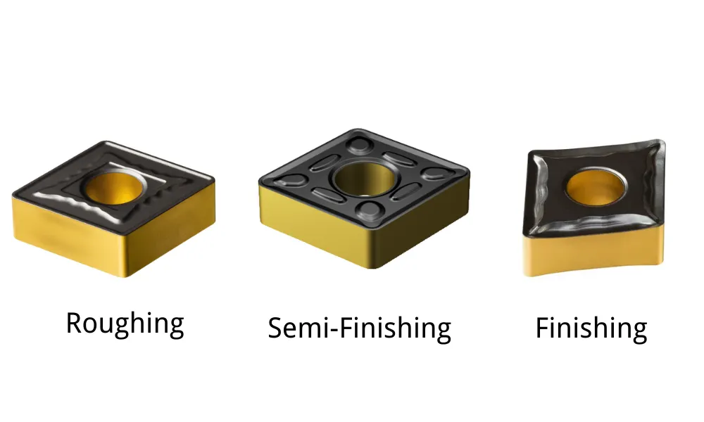
Большинство геометрий токарных инструментов можно отнести к трем общим группам применения.
| Характеристика | Геометрия отделки | Средняя геометрия | Геометрия черновой обработки |
| Типичный рацион | Низкий | Средний | Высокий |
| Типичная глубина реза | Маленький | Средний и широкий диапазон | Большой |
| Склонность к раке | Более позитивный | Умеренно позитивная или сбалансированная | От нейтрального до не слишком положительного |
| Передовые технологии | Sharp | Сбалансированный | Усиленный |
| Брусок для заточки кромок | Маленький | Средний | Больше или обеспечивающие лучшую защиту |
| Силы резания | Нижний | Умеренный | Выше |
| Возможности обработки поверхности | Высокий | Хорошо | Вторичный приоритет |
| Возможность прерываемого реза | Ограниченный | Умеренный | Выше |
| Наилучшее применение | Легкая отделка и тонкие детали | Производство общего назначения | Интенсивная обработка |
Компания «Сандвик» описывает геометрии для чистовой обработки как решения с острыми кромками, предназначенные для малых подач и небольшой глубины резания, геометрии среднего типа — как универсальный вариант, а геометрии для черновой обработки — как более прочные комплекты, разработанные для более высоких подач и более интенсивного резания.
Финишные стружколомки
Фреза с отводом стружки для чистовой обработки предназначена для работы с тонкой стружкой.
К типичным характеристикам относятся:
- узкие элементы системы управления стружкой, расположенные вблизи режущей кромки;
- положительный угол наклона;
- острая режущая кромка;
- небольшой брусок для заточки;
- небольшие усилия резания.
Обычно его выбирают для:
- небольшая глубина реза;
- незначительные подачи;
- тонкостенные детали;
- установки с низкой жесткостью;
- прецизионная обработка;
- области применения, требующие высокого качества поверхности.
Как правило, геометрия чистовой обработки не должна использоваться для грубой обработки с большим объемом материала или для интенсивного прерывистого резания. Ее острая кромка может сколоться или сломаться под нагрузками, на которые она не рассчитана.
Средние стружкоразрушители
Средний отломщик стружки обеспечивает наиболее широкий спектр применения в универсальных целях.
Часто это первая геометрия, которую следует проверить, когда:
- работа системы стабильна;
- подача и глубина реза умеренные;
- важны как контроль над чипом, так и прочность кромок;
- деталь предусматривает более одной глубины реза;
- Одна заготовка должна подвергаться полуфинитной и общей токарной обработке.
Средняя геометрия не всегда является оптимальным выбором для любой задачи. При использовании с подачей или глубиной реза ниже минимальных значений она все равно может приводить к образованию длинной стружки.
Стружеотводящие элементы для черновой обработки
Стружколом для черновой обработки предназначен для:
- большая глубина реза;
- более высокие скорости подачи;
- интенсивная обработка;
- кованые или литые поверхности;
- прерывистая резка;
- высокие нагрузки на режущие кромки.
Как правило, он сочетает в себе увеличенную площадь режущей кромки с усиленным краем, более широкой опорной поверхностью или более тяжелым хоном.
Использование геометрии черновой обработки для чрезвычайно легкого чистового реза может привести к:
- трение вместо чистого сдвига;
- увеличение режущих усилий;
- некачественная обработка поверхности;
- чрезмерная жара;
- ненадлежащий контроль стружки, поскольку стружка слишком тонкая, чтобы войти в паз.
Когда лучше использовать плоскую вершину или слабый струголом
Не всегда требуется мощный струголом.
Материалы, естественным образом образующие мелкие щебень
Серый чугун и некоторые легкообрабатываемые медные сплавы по своей природе дают короткую стружку. В таких случаях стружколомление может иметь меньшее значение, чем:
- прочность кромки;
- устойчивость к истиранию;
- количество рабочих режущих кромок;
- стоимость за грань.
Поэтому целесообразно использовать вставку с плоской вершиной или с незначительным изгибом.
Тяжёлая резка с перерывами
Глубокие канавки, поперечные отверстия, шероховатости и прерывистые поверхности подвергают кромку ударам.
Сложная, глубоко вырезанная канавка может уменьшить объем материала, поддерживающего режущую кромку. Более прочная геометрия с плоской вершиной или усиленная геометрия может снизить риск разрушения кромки.
Задачи, требующие очень низкого режущего усилия
При механической обработке:
- тонкие стенки;
- детали малого диаметра;
- тонкие черты лица;
- нестабильные конфигурации;
- цветные металлы;
Для минимизации прогиба детали и вибрации предпочтительна может оказаться четкая, открытая геометрия с относительно слабым удержанием стружки.
Операции, в которых качество поверхности имеет решающее значение
Стружка, которая резко закручивается в сторону заготовки, может поцарапать только что обработанную поверхность.
Менее ограничивающая геометрия, более удачное направление стружки или скорректированный поток охлаждающей жидкости могут обеспечить более чистую поверхность, даже если стружка будет немного длиннее.
Отсутствие агрессивного стругоразрушителя не обязательно является конструктивным недостатком. Это может быть правильным инженерным решением для конкретной операции.
[Внутренняя ссылка: Вставки с положительной и отрицательной граблиной]
Как условия резания влияют на эффективность работы стружколома
Струголом не может рассматриваться в отрыве от параметров резания.
Скорость подачи
Скорость подачи является одним из наиболее значимых факторов, влияющих на толщину стружки.
Слишком низкая подача:
- чип тонкий;
- чип может скользить по канавке без достаточного сгибания;
- могут возникнуть потертости и наросты по краям;
- могут образоваться длинные волокнистые кусочки.
Слишком высокая подача:
- рост нагрузки на передовые системы;
- чипы могут стать слишком короткими или резкими;
- вставка может отколоться;
- Мощность и устойчивость машины могут стать ограничивающими факторами.
Глубина среза
Глубина резания определяет, какая часть режущей кромки и геометрии стружколома участвует в процессе резания.
Глубина реза слишком мала:
- чип формируется в основном вокруг радиуса носа;
- чип может не достичь предусмотренного места разрыва;
- работа микросхемы становится нестабильной.
Слишком большая глубина реза:
- чип может превышать номинальную мощность автоматического выключателя;
- нагрузка на кромку увеличивается;
- может возникнуть затруднение при выводе микросхемы;
- при резке может задействоваться неподдерживаемый участок кромки.
Скорость резки
Скорость резания влияет на:
- температура;
- укреплённый край;
- поток материалов;
- износ инструмента;
- пластичность чипа.
Этот эффект зависит от материала.
В случае некоторых пластичных материалов увеличение скорости может уменьшить образование наплавленного кромки, но при этом может затруднить отламывание горячей стружки. В других случаях слишком низкая скорость способствует прилипанию и нестабильному образованию стружки.
Поэтому скорость следует регулировать в пределах диапазона, рекомендованного производителем шлифовального материала, а не использовать в качестве первой универсальной меры по устранению любой проблемы, связанной с стружкой.
Охлаждающая жидкость
Охлаждающая жидкость может влиять на:
- направление чипа;
- трение на поверхности граблей;
- температура микросхемы;
- укреплённый край;
- эвакуация чипа;
- термический удар.
Подача охлаждающей жидкости под высоким давлением с точным направлением струи особенно эффективна в тех случаях, когда длинные стружки трудно удалить. Ее не следует использовать для компенсации работы стружколома, работающего полностью за пределами рекомендуемого диапазона подачи и глубины резания.
Угол входа
Угол входа влияет на толщину и ширину стружки.
Как правило, меньший угол входа при одинаковой подаче приводит к образованию более тонкой и широкой стружки, тогда как больший угол входа — к образованию более толстой и узкой стружки. Это может привести к тому, что операция окажется в пределах или за пределами зоны действия стружколома.
Выбор скребка в зависимости от материала заготовки
ISO P: Сталь
Сталь зачастую является наиболее предсказуемой группой материалов при выборе стружколома, однако её поведение значительно варьируется в зависимости от содержания углерода, легирующих элементов и твердости.
Низкоуглеродистая сталь
Низкоуглеродистая сталь обладает пластичностью и часто образует длинные стружки и наплавленную кромку.
К полезным геометрическим характеристикам относятся:
- положительный наклон;
- острое режущее действие;
- надежное скручивание стружки при низкой и средней скорости подачи;
- антиадгезионное покрытие или обработка поверхности.
Если глубина резания крайне мала по сравнению с радиусом носка, стружка может не полностью зацепиться за стружколоматель.
Сталь со средним содержанием углерода и легированная сталь
Эти материалы, как правило, обеспечивают широкий диапазон рабочих условий для средних стружколомков.
Выберите геометрию в соответствии с:
- чистовая или черновая обработка;
- непрерывная или прерывистая резка;
- кованая или обработанная на станке поверхность;
- фактичная подача и глубина реза.
Высоколегированная или более твердая сталь
Более высокие температуры и режущие усилия могут сузить практический диапазон управления стружкой.
Может потребоваться более прочная режущая кромка и термостойкая марка стали, даже если форма стружколома кажется подходящей.
ISO M: Нержавеющая сталь
Аустенитная нержавеющая сталь — один из наиболее распространённых материалов, при обработке которых образуются длинные и сложные стружки.
Кроме того, он, как правило,:
- упрочнение при деформации;
- форма с укреплённым краем;
- выделяют большое количество тепла;
- приводить к износу в виде выемки;
- образуют твердые стружки, которые ударяются о инструмент или заготовку.
Рекомендуемые стартовые характеристики включают:
- положительный наклон;
- острая режущая кромка;
- специальный отбойник стружки для данного материала;
- постоянная глубина реза;
- достаточная подача материала для запуска дробилки;
- точно направленное подача охлаждающей жидкости.
Не следует многократно обрабатывать поверхность, подвергшуюся упрочнению, с использованием чрезмерно малой глубины резания.
Дуплексная нержавеющая сталь образует более прочные и твёрдые стружки и требует больших режущих усилий, чем многие аустенитные марки. В связи с этим прочность режущей кромки и стабильность технологического процесса приобретают ещё большее значение.
ISO K: Чугун
Серый чугун обычно образует короткие стружки, которые сами отламываются. Поэтому борьба со стружкой зачастую представляет меньшую сложность, чем борьба с абразивным износом, пылью и износом режущих кромок.
Геометрию с утолщением или плоской вершиной можно выбрать в следующих случаях:
- разрез стабилен;
- материал естественным образом распадается на фрагменты;
- требуется максимальная прочность режущей кромки.
Ковкий чугун и чугун с уплотнённым графитом ведут себя не совсем так же, как серый чугун. При их обработке могут образовываться более длинные стружки, возникать более высокие усилия и выделяться больше тепла, поэтому следует выбирать специальную геометрию и марку режущего инструмента.
ISO N: Алюминий и цветные металлы
Алюминий требует небольших усилий резания и обладает высокой устойчивостью к прилипанию материала.
К типичным геометрическим особенностям относятся:
- очень высокий наклон;
- очень острая режущая кромка;
- полированная верхняя поверхность;
- большое пространство для микросхем;
- минимальная заточка кромок;
- карбид без покрытия, карбид с DLC-покрытием или PCD в зависимости от области применения.
Чистый и мягкий алюминий может образовывать очень длинные, липкие стружки. Литейные алюминиевые сплавы, как правило, облегчают контроль за стружкой, хотя алюминий с высоким содержанием кремния обладает высокой абразивностью, что может оправдать использование инструментов из ПКД.
Латунь и некоторые бронзовые сплавы образуют более короткие стружки, поэтому для их обработки может потребоваться менее интенсивная стружколомка.
Например, в геометриях инструментов Iscar, предназначенных для обработки алюминия, используется большой положительный угол наклона, шлифованная и полированная поверхность наклонной грани, а также острая режущая кромка, что позволяет снизить адгезию и режущие усилия.
[Внутренняя ссылка: Вставки CCGT для алюминия]
[Внутренняя ссылка: Вставки DCGT для обработки алюминия]
ISO S: Титан и жаропрочные суперсплавы
Титан, суперсплавы на основе никеля и сплавы на основе кобальта сохраняют значительную прочность при высоких температурах.
К числу типичных проблем относятся:
- концентрированное тепло резания;
- износ пазов;
- укреплённый край;
- высокие динамические режущие усилия;
- длинные или сегментированные стружки, которые трудно контролировать;
- внезапный отказ кромки.
К подходящим пусковым характеристикам часто относятся:
- положительная геометрия резания;
- острая, но надлежащим образом укреплённая кромка;
- прочная карбидная основа;
- PVD нанесение покрытия, где это необходимо;
- регулируемая скорость резания;
- охлаждающая жидкость под высоким давлением;
- постоянное взаимодействие.
При работе с этими материалами отломщик стружки не следует выбирать в отрыве от подготовки режущей кромки, марки инструмента и схемы подачи смазочно-охлаждающей жидкости.
ISO H: Закаленные материалы
Твердые стали обычно подвергаются чистовой токарной обработке с использованием CBN, керамики или специальных твёрдосплавные вставки.
Контроль за стружкой может быть относительно несложным, поскольку данный материал часто образует короткую или сегментированную стружку. Более серьезные проблемы могут включать:
- передовая прочность;
- износ боковых поверхностей;
- износ кратера;
- термическая стабильность;
- согласованность измерений;
- целостность поверхности.
В некоторых пластинках CBN используются лазерные или формованные стружколомы, которые позволяют улучшить направление стружки и снизить режущие усилия при легкой чистовой обработке. Геометрия должна быть специально разработана с учетом хрупкости материала режущего инструмента.
[Внутренняя ссылка: Почему для твердого точения следует использовать твердосплавные CBN-вставки?]
Устранение неисправностей, связанных с ненадлежащим управлением чипом
Перед заменой пластины убедитесь, что текущие условия резания соответствуют таблице счищателей стружки, предоставленной производителем.
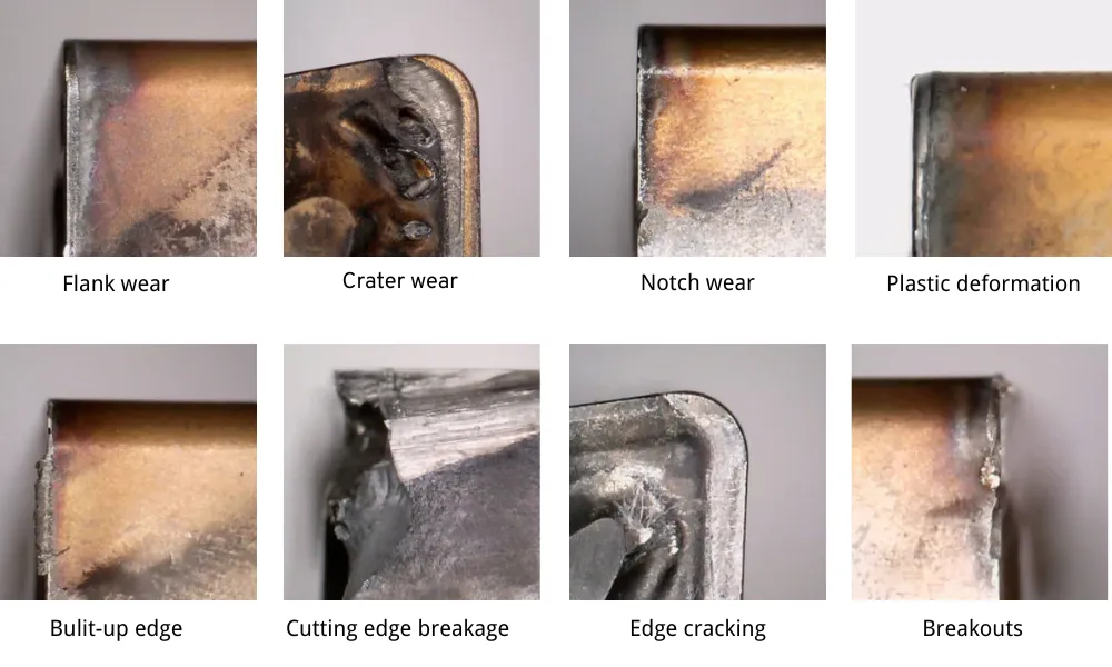
| Симптом | Возможные причины | Корректирующие меры |
| Длинные непрерывные стружки | Подача слишком низкая; глубина реза слишком мала; зазор слишком большой; стружколоматель не включен | Увеличьте подачу в пределах рекомендуемого диапазона; по возможности увеличьте глубину резания; выберите геометрию, обеспечивающую более эффективное удаление стружки при низкой подаче |
| Укладка «птичьего гнезда» вокруг инструмента | Неправильное направление стружки; длинные пластичные стружки; неправильное направление подачи охлаждающей жидкости | Оптимизировать направление стружки; использовать сквозную подачу охлаждающей жидкости или систему подачи под высоким давлением; изменить геометрию отбойника; пересмотреть угол входа держателя |
| Чрезвычайно короткие твёрдые стружки | Скорость подачи слишком высокая; удерживающее усилие стружки слишком сильное; геометрия слишком агрессивная | Уменьшите подачу; выберите более открытую или положительную геометрию; проверьте режущую кромку на наличие повреждений |
| Осколки царапают готовую поверхность | Стружка скручивается в сторону детали; плохая эвакуация; охлаждающая жидкость неправильно отводит стружку | Изменить направление чипа; перенаправить поток охлаждающей жидкости; выбрать геометрию с меньшим сопротивлением; изменить траекторию подхода инструмента |
| Установите стружки на режущую кромку | Слишком острая геометрия; прерывистый рез; чрезмерная подача или глубина реза; нестабильная настройка | Выберите более прочную геометрию и более высокопрочную марку материала; уменьшите нагрузку; сократите вылет; улучшите закрепление заготовки |
| Накладной край | Слишком низкая скорость; слишком тупая геометрия; неподходящее покрытие; плохая смазка | Используйте инструмент с более острой положительной геометрией; регулируйте скорость в пределах рекомендуемых значений; улучшите качество охлаждающей жидкости или смазки; используйте материал с антиадгезионными свойствами |
| Некачественная обработка поверхности при сохранившейся кромке | Геометрия черновой обработки, применяемая при легком резании; задирание; повторное резание стружки; вибрация | Используйте геометрию чистовой обработки; обеспечьте минимальную подачу; улучшите отвод стружки; проверьте радиус вершины и жесткость |
| По мере износа пластины ухудшается контроль над чипом | Износ кратера приводит к изменению геометрии угла наклона; кромка становится закругленной; покрытие разрушается | Ранее установить вставку; проверить степень наклона и скорость; проверить подачу охлаждающей жидкости |
| Осколки ударяются о кромку и повреждают её | Неправильное расположение чипа; слишком сильное сжатие; резкое отрывание от заготовки | Замените стругорез; отрегулируйте угол наклона держателя или подачу охлаждающей жидкости; уменьшите интенсивность скручивания |
| Форма чипа изменяется по периметру детали | Переменная глубина реза; изменение угла входа; прерывистые элементы; различия в материалах | Используйте геометрию с более широким диапазоном; стабилизируйте глубину реза; при необходимости программируйте отдельные проходы |
| Высокие режущие усилия или нагрузка на шпиндель | Угол наклона слишком большой; зазоры между режущими кромками и заземлением или заточки слишком велики; подача или глубина резания чрезмерны | Выберите более подходящую геометрию; уменьшите параметры резания; проверьте высоту центра и выравнивание держателя |
| После замены пластин возникает дребезг | Новая геометрия создает более высокие нагрузки; радиус носовой части слишком велик; отсутствует опора на кромку или неправильная настройка | Используйте геометрию, обеспечивающую меньшее усилие; уменьшите вылет; улучшите зажим; пересмотрите радиус носка и направление резания |
Рекомендуемый порядок устранения неисправностей
Если чипы не ломаются должным образом, проверьте переменные в следующем порядке:
- Уточните полное обозначение пластины и стругоразрушителя.
- Убедитесь, что подача и глубина реза находятся в пределах значений, указанных в каталоге.
- Уточните материал и твердость заготовки.
- Проверьте режущую кромку на наличие износа или наслоений материала.
- Убедитесь в правильном расположении держателя, высоте центра и угле входа.
- Проверьте давление и направление потока охлаждающей жидкости.
- Проверить стабильность станка и закрепления заготовки.
- Изменяйте геометрию стругоразрушителя только после того, как вы усвоите вышеуказанные условия.
- Измените класс вставки, если фактическим ограничивающим фактором является износ, нагрев или прочность кромки.
- Зафиксируйте параметры, обеспечившие успех, для использования в будущем производстве.
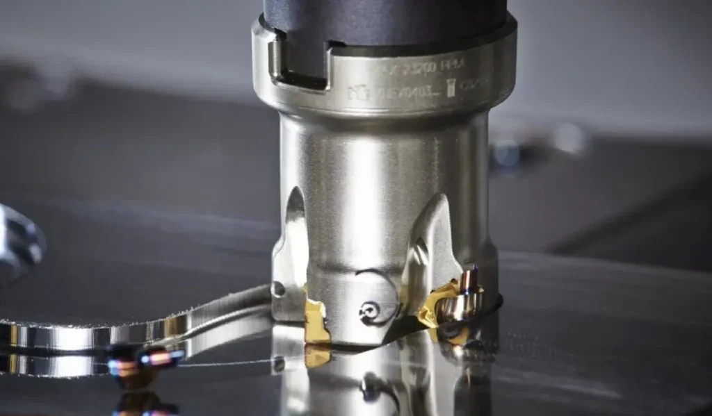
Используются ли в фрезерных пластинах также стружколомы?
Да, хотя производители фрезерного оборудования часто используют более широкий термин вставить геометрию а не рассматривать отломщик стружки как отдельный элемент.
При токарной обработке режущая кромка может постоянно находиться в контакте с заготовкой, поэтому обеспечение непрерывного удаления стружки является одной из основных задач.
При фрезеровании:
- разрез прерывается;
- толщина стружки изменяется при входе и выходе зуба;
- стружка часто отрывается сама по себе, как только режущая кромка отрывается от заготовки;
- Удаление стружки, режущее усилие и прочность кромки могут иметь большее значение, чем предотвращение разрыва непрерывной стружки.
Геометрия верхней части фрезерной пластины по-прежнему оказывает влияние:
- эффективный угол наклона;
- режущая сила;
- поток микросхем;
- сопротивление укреплённой кромке;
- прочность кромки;
- отделка поверхности.
Геометрические формы фрезерных инструментов обычно подразделяются на следующие категории:
- геометрия из алюминия или цветных металлов;
- геометрия, обеспечивающая хорошее рассечение;
- геометрия общего назначения;
- геометрия для тяжелых условий эксплуатации.
При выборе фрезерная вставка геометрия, использование:
- подача на зуб,
fz; - осевая глубина реза,
ap; - радиальная ширина реза,
ae; - угол входа режущего инструмента;
- диаметр режущего инструмента;
- количество зацепленных зубьев;
- стабильность машины.
Не следует напрямую применять таблицу счищателей стружки при токарной обработке к фрезерная вставка.
[Внутренняя ссылка: Как правильно выбрать фрезерные пластины]
[Внутренняя ссылка: Фрезерные пластины по области применения]
Информация, необходимая для выбора подходящего отломщика стружки
Обращаясь к поставщику с просьбой порекомендовать вставку, укажите не только базовый код ISO.
Отправить:
- полное обозначение текущей вставки;
- указать производителя, если известно;
- обозначение держателя инструмента;
- внешняя, внутренняя, торцевая, профилирующая или канавкорезная обработка;
- материал заготовки и точная марка;
- твердость заготовки;
- глубина реза;
- подача за один оборот;
- скорость резания;
- непрерывная или прерывистая резка;
- сухое охлаждение, затопление или охлаждение под высоким давлением;
- текущая форма микросхемы;
- текущий износ или характер отказа;
- требуемая чистота поверхности;
- фотографии вставки, держателя, заготовки и стружки;
- необходимое количество.
Фотография чипов зачастую бывает полезнее, чем такое утверждение, как “вставка не работает”.”
Часто задаваемые вопросы
Является ли струголом просто канавкой на пластине?
Нет. В практической конструкции режущих пластин стружколоматель является частью комплексной геометрии режущей кромки, которая включает в себя переднюю поверхность, затылочную поверхность, фаску и подготовку кромки.
Все ли твердосплавные пластины имеют стружколок?
Нет. Некоторые пластины имеют плоские режущие поверхности или обладают очень слабыми стружкообразующими характеристиками. Они могут подходить для материалов, при обработке которых стружка образуется естественным образом короткой, для тяжелого прерывистого резания или для задач, в которых приоритетом является прочность режущей кромки.
Существует ли стандартизация кодов стругоразрушителей?
Нет. Часть обозначения вставки, соответствующая стандарту ISO, стандартизирует такие характеристики, как форма, зазор, допуск, размер и радиус передней кромки. Суффиксы, обозначающие струголом, и названия геометрических форм, как правило, зависят от конкретного производителя.
Какой отломщик стружки следует использовать для чистовой обработки?
Используйте геометрию чистовой обработки, рассчитанную на конкретный материал заготовки, а также на заданные величины подачи и глубины резания. Как правило, она отличается более острой кромкой и меньшими режущими усилиями по сравнению с геометрией черновой обработки.
Какой отломщик стружки лучше всего подходит для общего токарного обработки?
Геометрия среднего или универсального типа, как правило, является первым выбором для стабильного токарного обработки со средней нагрузкой. При этом указанные в каталоге параметры должны соответствовать фактическим значениям подачи и глубины резания.
Почему при резке моей вставкой образуются длинные нитевидные стружки?
К числу наиболее распространенных причин относятся подача, не достигающая минимального диапазона, установленного для стружколома, слишком малая глубина резания, чрезмерно открытая геометрия, неправильный угол входа или неподходящее направление подачи охлаждающей жидкости.
Может ли увеличение подачи улучшить измельчение стружки?
Да. При увеличении подачи образуется более толстая стружка, которая может более эффективно взаимодействовать с стружколомом. Подача должна оставаться в пределах, допускаемых пластинкой, сортом, станком и узлом.
Всегда ли очень короткие фишки лучше?
Нет. Чрезвычайно короткие или раздробленные стружки могут свидетельствовать о чрезмерном удержании стружки и высокой нагрузке на режущую кромку.
Можно ли использовать разные стругоотводящие элементы с вставкой одной и той же формы?
Да. CNMG, WNMG, пластина, DCMT и другие серии вставок предлагаются с различными типами стружколомов для разных материалов и диапазонов обработки.
Влияет ли отломщик стружки на качество поверхности?
Да. Это влияет на режущее усилие, направление стружки, остроту режущей кромки, а также на то, соприкасается ли стружка с обрабатываемой поверхностью. Однако на качество поверхности также влияют радиус передней кромки, подача, биение, вибрация и износ пластины.
Что следует сменить в первую очередь: чипбрейкер или марку пластины?
Следует менять стружколом, если основной проблемой является образование стружки, режущее усилие или диапазон геометрических параметров. Следует менять марку, если основной проблемой является износостойкость, термостойкость или ударная вязкость. Во многих случаях оба параметра необходимо выбирать в качестве согласованной комбинации.
Нужны ли стружколомы для фрезерных пластин?
В фрезерных пластинах используются различные геометрические формы, выполняющие во многом одинаковые функции. Однако их следует выбирать из таблиц, предназначенных специально для фрезерования, с учетом подачи на зуб, осевой глубины резания и радиального зацепления.
Контрольный список для окончательного отбора
Перед заказом вставки убедитесь, что:
- геометрия рассчитана с учетом материала заготовки;
- геометрия соответствует чистовой, средней или черновой обработке;
- подача и глубина резания находятся в пределах карты контроля стружки;
- подготовка кромки достаточно прочная для выполнения реза;
- класс вставки соответствует требованиям по термостойкости, износостойкости и стабильности;
- угол наклона режущей кромки и радиус носка обеспечивают получение стружки желаемой формы;
- охлаждающая жидкость может поступать в зону резания;
- Суффикс вставки был проверен в соответствующем каталоге производителя.
Цель заключается не в том, чтобы создать чип максимально небольшого размера.
Цель состоит в том, чтобы достичь устойчивого баланса между:
- контролируемое формирование кристаллов;
- умеренные усилия резания;
- достаточная прочность в поперечном сечении;
- приемлемый срок службы инструмента;
- надежное качество поверхности;
- безопасный вынос стружки.
Нужна помощь в подборе стружколомщика для существующей операции токарной обработки? Пришлите полный код пластины, модель держателя, материал заготовки, параметры резания и фотографию стружки для проверки совместимости и геометрии.