Internal Vs External Thread

Threads are the unsung heroes of mechanical engineering, quietly holding the modern world together. From the microscopic screws securing your smartphone’s motherboard to the massive structural bolts stabilizing a suspension bridge, all of these connections rely on a perfect geometric pairing. At the heart of this mechanical handshake is the fundamental distinction between external threads and internal threads.
While they must share the exact same theoretical thread profile (like a metric or unified standard) to interlock seamlessly, their physical geometry in the real world is entirely inverted.
An external thread is machined onto the outside surface of a cylinder or cone—think of a classic bolt or a screw. For an external thread, the geometric logic is straightforward: the major diameter is the crest-to-crest distance, representing the maximum outer width of the cylinder. Conversely, the minor diameter is measured at the roots of the threads, representing the thinnest and most structurally vulnerable core of the part.
An internal thread, on the other hand, is cut into the inside surface of a hole, exactly like the threads inside a nut or an engine block. Here, the geometric perspective flips. The major diameter is now hidden deep within the roots of the thread—it is the widest part of the cut inside the hole. The minor diameter represents the crests of the internal threads, which, in practical machining terms, directly corresponds to the size of the initial hole you must drill before cutting the threads.
Understanding this “inverted” geometric relationship is not just a theoretical exercise; it is the crucial first step for any engineer or machinist. It dictates everything from how we calculate tolerances to the specific cutting tools we select on the shop floor.
Function and Mating Relationship
Function & Mating Role
- External Thread (Male thread / External screw thread): Acts as the active, inserting component. It is typically on the bolt, screw, stud, lead screw, or any male fastener that engages into the internal thread.
- Internal Thread (Female thread / Internal screw thread): Acts as the passive, receiving component. It is typically found in nuts, tapped holes in housings, threaded inserts, flanges, or any part that accepts and holds the external thread.
Load-Bearing Characteristics During Tightening / Axial Loading When a threaded joint is loaded in tension (pulling apart), the forces act differently on each side due to geometry:
| Aspect | External Thread (on bolt/screw) | Internal Thread (in nut/hole) |
|---|---|---|
| Primary load on thread flank | Thread flank transfers axial force | Thread flank transfers axial force |
| Stress on thread tooth | Tooth crest (top) is compressed | Tooth root (bottom) is compressed |
| Stress on thread root | Tooth root (fillet area) experiences tensile stress (most critical area) | Tooth crest experiences tensile stress |
| Typical stress concentration location | High stress concentration at thread root fillet (notch effect + tensile load) | Stress more distributed, but first engaged threads bear disproportionately high load |
| Load distribution | More uniform across engaged threads (but still highest on first few threads) | Highly non-uniform; first 3–5 threads often carry 60–80% of total load (depending on pitch, material, fit) |
| Advantage in strength | Generally higher tensile strength capacity (solid cross-section, root area larger relative to stress) | Lower inherent strength due to reduced material around hole and hoop stress risk |
| Common failure mode (under overload / fatigue) | Thread root fracture, fatigue crack initiation at root fillet, tensile rupture of shank | Thread stripping (shear failure of internal threads), nut dilation / bursting, pull-out failure |
Key Engineering Insight
- In most standard bolted joints, engineers design so that the external thread (bolt) fails first in tension (ductile necking/breakage of shank), rather than stripping the internal thread — this is considered a safer, more predictable failure mode (bolt breaks but nut/housing remains intact).
- Internal threads are more prone to stripping because:
- The material supporting the threads is annular (less cross-sectional area).
- Hoop (circumferential) tensile stress tends to expand the nut/hole.
- Load is concentrated on the first few threads.
- In high-strength applications (Grade 8/10.9/12.9 bolts), the nut is often made slightly softer than the bolt to encourage bolt failure over nut stripping.
External threads typically handle tensile loads via root tension and offer higher overall strength, while internal threads bear compressive loads on the root but are more vulnerable to stripping and hoop bursting — therefore, design priority is usually given to protecting the internal thread from overload.
Machining Methods and Process Routes
When we move from geometric theory to the reality of the machine shop floor, the differences between external and internal threads become starkly physical. The entire manufacturing strategy for a thread is dictated by one critical factor: accessibility. This single variable determines how easily a cutting tool can engage the material, how effectively coolant can reach the cutting zone, and, most importantly, where the metal chips will go.
External Machining: The “Open Air” Advantage
Machining an external thread is generally a highly accessible process. Because the operation happens on the outside of a cylinder, it is an “open” cutting environment. Coolant can be flooded directly onto the cutting edge, and metal chips can naturally fall away from the workpiece.
This freedom allows for a wide variety of high-efficiency manufacturing methods:
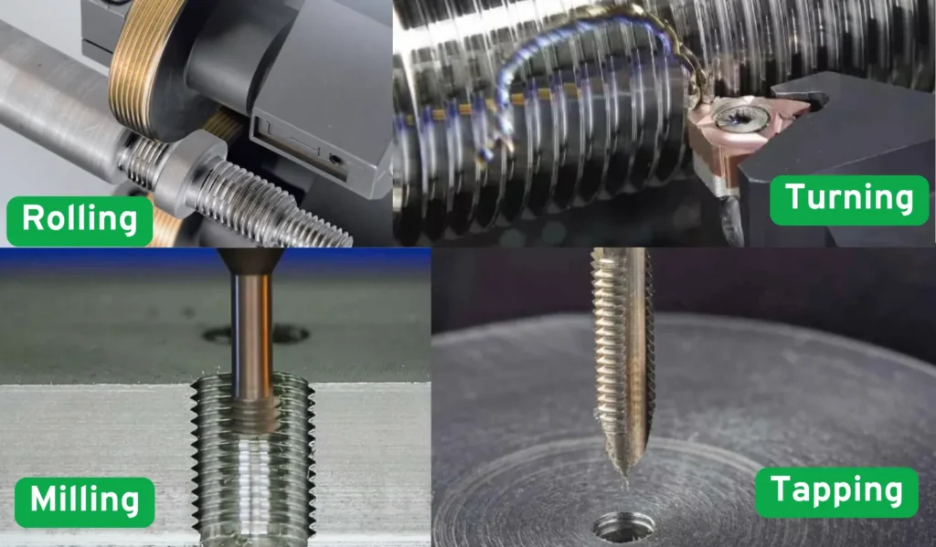
- Thread Turning: Using a lathe with a single-point threading insert is the standard for precision and flexibility.
- Thread Rolling: For mass production and high-strength fasteners (like automotive bolts), rolling is the undisputed king. Instead of cutting metal, hardened steel dies press and cold-forge the thread profile into the blank. This produces zero chips and significantly increases the thread’s fatigue strength through work hardening.
- Threading with Dies: Often used for manual repairs or quick setups on manual lathes.

Internal Machining: The Claustrophobic Challenge
Cutting internal threads—especially in blind holes (holes that do not go all the way through the part)—is a completely different beast. The machining environment is enclosed and claustrophobic. Coolant struggles to reach the bottom of the hole, and chip evacuation becomes the engineer’s primary enemy. A packed chip can instantly snap a cutting tool, destroying both the tool and potentially the expensive workpiece.
To navigate these restrictions, machinists rely on specialized techniques:
- Tapping: The most common method for small to medium holes. Taps are specialized rotary tools that cut threads as they are driven into the hole. For blind holes, spiral-fluted taps are heavily utilized because their geometry actively pulls chips up and out of the hole, much like a drill bit.
- Internal Thread Turning (Boring): Used for larger holes on a lathe. The major challenge here is tool rigidity. The cutting insert must be mounted on a boring bar that reaches inside the hole. If the hole is deep, the high length-to-diameter (L/D) overhang ratio makes the tool highly susceptible to vibration and “chatter,” which ruins the thread finish.
- Thread Milling: An advanced CNC technique where a rotating milling cutter spirals down the hole. It generates smaller chips that are easily flushed out and is highly favored for machining hard materials or very large internal threads where a tap would require too much torque.
| Dimension | External Thread (Male / External) | Internal Thread (Female / Internal) | Difficulty / Cost / Risk Comparison | Typical Application Notes |
|---|---|---|---|---|
| Main Processing Methods | 1. Thread Rolling (most preferred for mass production) 2. Single-Point Turning (lathe) 3. Thread Rolling Dies / Planetary Dies (die rolling) 4. Thread Milling 5. Thread Grinding (for ultra-precision) | 1. Forming / Flow Tapping (chipless cold forming) 2. Thread Milling (highly flexible) 3. Cutting Tapping (traditional) 4. Single-Point Internal Turning (lathe) 5. Broaching / Pushing (rare, large diameters) | Internal significantly harder overall | External: rolling dominates; Internal: forming/milling rising fast |
| Tool Rigidity Requirement | Low (short overhang, open external surface) | Very high (long slender tool/tap overhang, prone to vibration/breakage) | Internal >> External | Small-diameter internals (M3 and below) are toughest |
| Chip Evacuation Difficulty | Extremely easy (chips fly outward, open space) | Extremely difficult (enclosed hole, chips can jam, pack, and break tool) | Internal >> External | Blind-hole internals are the biggest headache |
| Coolant / Lubrication Access | Easy (external flood or through-tool possible, reaches cutting zone directly) | Difficult (requires through-tool coolant, high-pressure, or MQL; otherwise overheating/sticking) | Internal much harder | Tough materials (titanium, stainless) need high-pressure for internals |
| Tool Life | Longer (rolling almost unlimited; turning/milling good) | Shorter (especially small-diameter cutting taps: often only dozens to hundreds of holes) | Internal 5–20× shorter in many cases | High-volume internal tapping requires frequent tool changes |
| Cycle Time / Processing Speed | Fast (rolling: seconds per part; turning also quick) | Slower (tapping needs low speed + peck/reverse; milling flexible but longer path) | Internal 30%–200% slower | Mass external rolling has overwhelming speed advantage |
| Small Diameter Limit (Metric) | M1.0–M0.8 still relatively feasible | M1.0 and below very challenging; M1.2–M1.4 already difficult; M0.8- often needs special processes | Internal more limited | Medical/aerospace tiny threads often designed external |
| Most Difficult Specifications | Large coarse pitch, ultra-long threads, thin-wall tubes (vibration/deformation risk) | Small-diameter deep holes + fine pitch, blind holes, high-hardness materials (HRC>40), superalloys (Inconel, Ti) | — | Internal blind + fine + difficult-to-cut = nightmare combo |
| Surface Finish & Strength | Rolling best (cold work hardening, Ra 0.2–0.4 µm, fatigue strength +30–50%) | Forming tapping best (grain refinement, high strength like rolling); cutting tapping inferior | External rolling > Internal forming > others | High-fatigue parts prioritize rolled external or formed internal |
| Cost Ranking (Mass Production) | Rolling lowest → Die rolling → Turning/Milling → Grinding | Forming tapping lowest (chipless) → Thread milling (flexible but expensive tools) → Cutting tapping (cheap tools but short life) | Internal generally higher cost | External rolling is the cost/performance king for volume |
| Common Problems & Risks | Poor blank surface before rolling → die breakage Thin-wall rolling/turning → ovality/expansion Vibration causing pitch errors | Tap breakage (most common disaster) Blind-hole incomplete last threads Spring-back oversize after forming/cutting Poor chip evacuation → galling/breakage | Internal risk far higher | Broken tap removal in internals can be extremely expensive |

The Inverse Logic of Thread Inspection
In the world of precision manufacturing, you cannot control what you cannot measure. Just as the geometric features of external and internal threads are inverted, the tools used to inspect them are exact physical opposites of the parts they are measuring. To verify the quality of a thread on the shop floor, machinists essentially use a “perfect” mating part to test the newly machined one, relying heavily on the Go/No-Go principle.
Inspecting External Threads
Surrounding the Part When assessing an external thread like a bolt, the primary concern is whether it will smoothly thread into a standard nut without being too loose.
- Thread Ring Gauges: The standard shop-floor tool is the thread ring gauge. It comes in a pair: the “Go” ring and the “No-Go” ring. The Go ring mimics a perfectly sized nut at its maximum material condition; it must thread onto the bolt completely without excessive force. The No-Go ring checks the minimum pitch diameter limit and should not thread on more than two turns.
- Precision Measurement: For exact numerical data rather than a simple pass/fail, quality control inspectors use a Thread Micrometer equipped with special V-shaped anvils to measure the pitch diameter directly. In high-precision laboratory settings, the Three-Wire Method is the gold standard. By placing three precision-ground wires into the thread grooves and measuring across them, engineers can calculate the true pitch diameter with extreme accuracy.
Inspecting Internal Threads
Probing the Depths Inspecting a threaded hole presents the same accessibility challenges as machining it. You cannot easily see inside the hole, so you must rely entirely on tactile feedback and specialized probes.
- Thread Plug Gauges: The inverse of the ring gauge, the thread plug gauge looks like a highly precise, hardened steel bolt. The “Go” end must thread all the way to the bottom of the tapped hole smoothly, proving that the major and pitch diameters are large enough to accept a standard bolt. The “No-Go” end verifies that the hole wasn’t cut too large.
- The Internal Measurement Challenge: Getting an actual numerical measurement of an internal pitch diameter is notoriously difficult. While specialized internal thread micrometers exist, they are delicate and cumbersome. Often, for critical aerospace or medical components, verifying the internal geometry requires casting a mold of the hole’s interior or using an advanced Coordinate Measuring Machine (CMM) with specialized styli.

Tolerances and Fits
Even if an external bolt and an internal tapped hole are machined perfectly according to their theoretical profiles, they still might not screw together. Why? Because mechanical assemblies require a tiny, controlled amount of “invisible space” to function—allowance for lubrication, anti-corrosion plating, or simply the ability to be assembled by hand without binding. This microscopic buffer zone is governed by the rigorous rules of Tolerances and Fits.
In the widely used Metric (ISO) thread system, the distinction between internal and external threads is immediately obvious in the engineering blueprints, denoted simply by the case of the letters used.
- External Thread Tolerances (Lowercase): The tolerance bands for external threads—like bolts and screws—are always designated with lowercase letters (e.g.,
g,h,e). For example, a common tolerance class for a standard bolt is 6g. The number “6” defines the grade of precision (the size of the tolerance window), while the letter “g” indicates the position of that window. A “g” position means the bolt’s maximum allowable size is intentionally cut slightly smaller than the theoretical basic size, guaranteeing a small clearance. - Internal Thread Tolerances (Uppercase): Conversely, internal thread tolerance bands are always designated with uppercase letters (e.g.,
G,H). A standard nut usually has a 6H tolerance. The “H” signifies that the smallest allowable size of the tapped hole is exactly equal to the theoretical basic size (it has a zero lower deviation).
When you pair a 6H internal thread with a 6g external thread, you create the most common standard clearance fit in engineering. The math guarantees they will never perfectly crash into each other, leaving just enough room for smooth operation.
Ultimately, these tolerances are applied most critically to the Pitch Diameter (the theoretical cylinder where the thread ridges and grooves have equal widths). For a standard metric thread, the theoretical pitch diameter (d2) is calculated using the nominal diameter (d) and the pitch (P) via the following formula:
d2 = d – 0.6495P
Controlling this specific dimension within its assigned tolerance band is the ultimate goal of both the machining and inspection processes discussed earlier.
Comprehensive System Comparison: External vs. Internal Threads
| Feature / Dimension | External Thread (Male) | Internal Thread (Female) |
| Geometric Location | Cut into the outer surface of a cylinder or cone. | Cut into the inner surface of a bored or drilled hole. |
| Typical Components | Bolts, machine screws, studs, lead screws, threaded shafts. | Nuts, threaded flanges, tapped holes in engine blocks or machine beds. |
| Major Diameter (D / d) | Represents the crest-to-crest distance. It is the largest outer dimension (Nominal Size). | Represents the root-to-root distance. It is the widest cut hidden deep inside the hole. |
| Minor Diameter (D1 / d1) | Represents the root diameter. It is the thinnest, most structurally vulnerable core of the fastener. | Represents the crest diameter. It directly dictates the tap drill size required before threading. |
| Primary Machining Processes | Single-point thread turning, thread rolling (cold forming/forging), threading with dies, thread milling. | Tapping (cut or form taps), internal thread turning (boring), thread milling. |
| Machining Environment | Open-air cutting. Excellent accessibility for coolant and natural chip evacuation via gravity/centrifugal force. | Enclosed/Claustrophobic. Especially in blind holes. High risk of chip packing and poor coolant penetration. |
| Tooling Challenges | Generally highly rigid tool setups. Tool wear is easy to monitor visually. | Prone to tool breakage due to packed chips. Internal boring bars suffer from high overhang (L/D) ratios, leading to vibration/chatter. |
| Shop-Floor Inspection | Thread Ring Gauges (Go/No-Go). The gauge envelops the machined part. | Thread Plug Gauges (Go/No-Go). The gauge probes the inside of the machined hole. |
| Precision Measurement | Thread micrometers (V-anvil), Three-Wire Method, optical comparators. | Specialized internal micrometers, Coordinate Measuring Machines (CMM), or internal cast molding. |
| ISO Metric Tolerances | Designated by lowercase letters (e.g., 6g, 6h). Controls the clearance allowance on the bolt. | Designated by uppercase letters (e.g., 6H, 6G). Controls the minimum size limit of the hole. |
FAQ
References & Further Reading
- Sandvik Coromant – Threading Knowledge Center A comprehensive guide from one of the world’s leading cutting tool manufacturers. It offers in-depth application advice on thread turning, thread milling, and insert selection for both external and internal operations. Website: https://www.sandvik.coromant.com/en-us/knowledge/machining-formulas-definitions/threading
- OSG Tooling – Tapping Troubleshooting and Guide OSG is a global leader in hole-making and threading tools. Their technical library is an excellent resource for understanding the complexities of internal thread tapping, proper tap drill size calculations, and solutions for chip evacuation in blind holes. Website: https://www.osgtool.com/resources/technical
- Engineers Edge – ISO Metric Thread Standards and Tolerances A vital reference for design engineers. This site provides detailed charts and engineering calculators for ISO metric thread profiles, including the exact dimensions for the 6H (internal) and 6g (external) tolerance classes discussed in this article. Website: https://www.engineersedge.com/hardware/metric-external-thread-sizes1.htm
- Machinery’s Handbook (Industrial Press) Often referred to as the “Bible of the Mechanical Industries.” While it is a printed handbook, it remains the ultimate authoritative source for the Three-Wire measurement method, thread geometry formulas, and material-specific galling prevention strategies. Website: https://industrialpress.com/machinerys-handbook/