Твердосплавные фрезерные пластины APMT
Сравните твердосплавные фрезерные пластины APMT1135 и APMT1604 по габаритам, стругоразрушителю, угловому радиусу, марке твердого сплава и совместимому корпусу фрезы. Выберите пластины для углового, торцевого и бокового фрезерования, вырезания карманов, наклонного фрезерования и других операций с использованием сменных пластин.
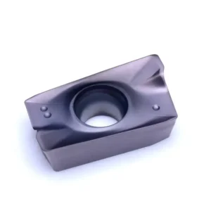

Что такое фрезерная пластина APMT?
APMT — это индексируемая фрезерная пластина в форме правильного параллелограмма, которая широко используется в системах угловых, боковых, карманных и некоторых торцевых фрезерных режущих инструментов.
Четыре буквы обозначают базовую форму в соответствии со стандартом ISO, зазор, допуск и конфигурацию отверстия/стругообразования. Последующие цифры и суффиксы определяют размер, радиус угла, геометрию и специфический для производителя струголом. Одного только четырехбуквенного кода серии недостаточно для подтверждения совместимости резака.
Как интерпретировать аббревиатуры PDER и PEER в обозначении APMT
PDER и PEER — это не обозначения стружкоотводителей. Они описывают код скребка, форму режущей кромки и направление резания. Код стружкоотводителя указывается отдельно после дефиса.
APMT1604PDER-M2PD это код стеклоочистителя, E представляет собой передовую форму, R — это направление вправо, а M2 — это финишный отломщик стружки.
APMT1604PEERФизическая культура — это код стеклоочистителя, за которым следует код формы кромки E и код справа R. Поскольку после дефиса не следует суффикс, обозначающий струговый нож, отобразите струговой нож следующим образом: / и рассматривать его как полуготовую версию, представленную в каталоге.
Полный перечень моделей и технических характеристик вставок APMT
Ниже приведены все модели APMT1135 и APMT1604, представленные в прилагаемом каталоге твердосплавных пластин. Размеры, стругоразрушители и доступные марки указаны с полным обозначением.
Как пользоваться таблицами
Сначала выберите платформу пластины из гнезда резака, а затем уточните полное обозначение, тип стругоразрушителя, радиус и доступный сорт. Точка, указанная в каталоге, была преобразована в сорт, указанный в последнем столбце.
Вставки APMT1135: все модели, размеры и марки
Каталог содержит четыре базовые модели APMT1135. Все четыре модели приведены ниже с указанием их габаритов, стругоснимающих элементов и вариантов материала.
| Обозначение в каталоге | L (мм) | Ш (мм) | T/S (мм) | D (мм) | RE (мм) | Чипбрекер | Этап механической обработки | Варианты оценок |
|---|---|---|---|---|---|---|---|---|
| APMT1135PDER-ZL | 11.30 | 6.25 | 3.60 | 2.80 | 0.80 | ZL | Полуфинишная обработка | D7320, D9920S |
| APMT1135PEER | 11.30 | 6.25 | 3.60 | 2.80 | 0.80 | / | Полуфинишная обработка | D530, D570, D580, D7320, D8420A, D9920S |
| APMT1135PDER-M2 | 11.30 | 6.20 | 3.50 | 2.80 | 0.80 | M2 | Отделка | D530, D570, D580, D7320, D8420A |
| APMT1135PDER-H2 | 11.30 | 6.20 | 3.50 | 2.80 | 0.80 | H2 | Черновая обработка | D530, D570, D580, D7320, D8420A |
Вставки APMT1604: все модели, размеры и марки
Каталог содержит девять моделей APMT1604, включая различные значения радиуса поворота PDER и отдельные варианты ZL, M2 и H2.
| Обозначение в каталоге | L (мм) | Ш (мм) | T/S (мм) | D (мм) | RE (мм) | Чипбрекер | Этап механической обработки | Варианты оценок |
|---|---|---|---|---|---|---|---|---|
| APMT1604PDER-ZL | 17.42 | 9.33 | 5.20 | 4.50 | 0.80 | ZL | Полуфинишная обработка | D7320, D9920S |
| APMT1604PEER | 17.42 | 9.33 | 5.20 | 4.50 | 0.80 | / | Полуфинишная обработка | D530, D570, D580, D7320, D8420A, D9920S |
| APMT160404PDER | 17.25 | 9.33 | 5.20 | 4.50 | 0.80 | / | Полуфинишная обработка | D530, D570, D580 |
| APMT160412PDER | 17.25 | 9.33 | 5.20 | 4.50 | 1.20 | / | Полуфинишная обработка | D530, D570, D580 |
| APMT160416PDER | 17.25 | 9.33 | 5.20 | 4.50 | 1.60 | / | Полуфинишная обработка | D530, D570, D580 |
| APMT160420PDER | 17.25 | 9.33 | 5.20 | 4.50 | 2.00 | / | Полуфинишная обработка | D530, D570, D580 |
| APMT160430PDER | 17.25 | 9.33 | 5.20 | 4.50 | 3.00 | / | Полуфинишная обработка | D530, D570, D580 |
| APMT1604PDER-M2 | 17.25 | 9.25 | 4.76 | 4.40 | 0.80 | M2 | Отделка | D530, D570, D580, D7320, D8420A |
| APMT1604PDER-H2 | 17.25 | 9.25 | 4.76 | 4.40 | 0.80 | H2 | Черновая обработка | D530, D570, D580, D7320, D8420A |
Совместимые режущие вставки и корпуса режущих инструментов серии APMT
Показатели поисковых запросов свидетельствуют о высоком интересе к режущим инструментам и корпусам режущих инструментов APMT. В приведенной ниже таблице приведена сопоставительная таблица, связывающая платформу режущих пластин с подтвержденными системами режущих инструментов из предоставленных каталогов.
Прямоугольные отрезные фрезы
Общие задачи по фрезерованию плечевых, боковых и карманных поверхностей, а также связанные с ними операции с использованием сменных режущих пластин.
Фрезы с более широкими плечами
Более крупная передовая платформа для черновой обработки и фрезерования уступов.
Фрезы для торцевой обработки под углом 75°
Система торцевого фрезерования с платформой APMT, выбранная на основе модели фрезы в сборе.
Компактная режущая система APMT
Мелкое и среднее фрезерование по плечу, сбоку и грубое фрезерование.
Увеличенная система резаков APMT
Средние и крупные операции по фрезерованию с переносом и удалению материала.
Глубокое фрезерование в плечевой и боковой частях
Системы с удлинёнными кромками и кукурузного типа для глубокой обработки плеч и бокового фрезерования.
Варианты стругоразрушителей APMT
Слово «чипбрейкер» — это суффикс, следующий за дефисом. Аббревиатуры PDER и PEER входят в структуру обозначения пластин и не должны использоваться в качестве названий чипбрейкеров.
Полуфабрикаты
Скобочку следует использовать, если полное обозначение заканчивается на PDER или PEER и за ним не следует отдельный суффикс. В данном каталоге модели, обозначенные скобочкой, используются для полуфинишной обработки.
Черновая обработка
H2 — это стружколоматель для черновой обработки, предназначенный для условий обработки с более жесткими кромками и повышенной нагрузкой.
Отделка
M2 — это финишный стружколок, предназначенный для более лёгкой резки и улучшения качества поверхности.
Полуфабрикаты
ZL — это полуфинишный срыватель стружки, обеспечивающий оптимальный баланс между объемом съема материала, стабильностью резания и качеством поверхности.
Вставки APMT в зависимости от материала заготовки
Выберите полную комбинацию размера, геометрии и марки. Не все марки доступны для всех обозначений APMT.
Сталь
Следует соблюдать баланс между прочностью кромки, износостойкостью и формированием стружки при фрезеровании с уступом, боковом и карманном фрезеровании.
Вставки для сталиНержавеющая сталь
Для снижения нагрева, упрочнения от деформации и образования наплавленного слоя следует использовать подходящие марки PVD и геометрию с меньшим усилием.
Вставки для нержавеющей сталиЧугун
Износостойкие марки обеспечивают стабильное фрезерование чугуна и подходят для определенных условий сухой обработки.
Вставки для чугунаСложные материалы
В условиях, требующих повышенной прочности и термостойкости, необходимо провести анализ условий эксплуатации, обеспечить стабильное сцепление и использовать проверенную комбинацию марок материалов.
Вставки из сложных материаловОбласти применения фрезерных пластин APMT
Фактическая производительность зависит от корпуса режущего инструмента. Технология APMT в основном применяется в системах фрезерования с положительным углом плеча и в системах с общими сменными пластинами.
Фрезерование плеча
Обработка горизонтального пола и вертикальной стены с помощью совместимых прямоугольных фрез.
Фрезерование торцов
Выбранные системы RAP-75 и аналогичные системы режущих инструментов для черновой и получистовой обработки плоских поверхностей.
Боковое фрезерование
Обрезка по периметру вдоль стен, ступеней и внешних элементов конструкции.
Карманное фрезерование
Черновая и профильная обработка внутри открытых карманов с использованием совместимого корпуса режущего инструмента.
Радиус угла и режущие кромки APMT
Один только код размера не позволяет полностью определить радиус угла. Используйте полное обозначение и значение RE из каталога.
Более большие радиусы углов, как правило, укрепляют кромку и позволяют выдерживать более высокую нагрузку, однако они также увеличивают режущее усилие и определяют минимальный внутренний угол, который можно изготовить.
Как выбрать вставку APMT
Запрос на расчет цены на услугу APMT Insert
Укажите полный код пластины, размер APMT1135 или APMT1604, тип стругоснимателя, марку, радиус угла, количество и текущую модель корпуса резака. Фотография гнезда резака или имеющейся пластины поможет подтвердить совместимость.