How to Drill Titanium? From Drilling Design to Parameter Tuning

Titanium alloys, an indispensable material in aerospace, medical implants, and chemical equipment, are highly favored for their high strength and corrosion resistance. However, how to drill titanium alloys? They pose a significant challenge to many engineers during drilling: rapid drill wear, tool breakage, and low machining efficiency are common problems.
In fact, solving these problems is not out of the question. This article will provide a systematic analysis of the complete technical solution for drilling titanium alloys, from tool design to practical parameters, helping you to overcome the challenges of titanium alloy machining completely.
Four Core Challenges in Titanium Alloy Drilling
Extremely high cutting temperatures are the primary challenge in machining titanium alloys. Titanium alloys have extremely low thermal conductivity, only 1/5 that of iron and 1/14 that of aluminum. This means that heat generated in the cutting zone is difficult to dissipate, leading to localized temperatures exceeding 1000°C. This not only shortens tool life but also easily causes thermal deformation of the workpiece.
Significant springback is another major challenge. Titanium alloys have a low elastic modulus (about half that of steel), causing elastic recovery of the hole wall after drilling, resulting in a “spring effect” that leads to hole shrinkage and dimensional deviations.
Titanium alloys have high chemical reactivity, reacting with tool materials at high temperatures to form deposits and diffusion alloys, which are detrimental to machining. This sticking phenomenon is particularly pronounced when the hardness is below HB300.
Furthermore, titanium alloy chips tend to stick together and are difficult to remove, easily forming built-up edges at the tool tip. These built-up edges periodically detach, carrying away tool material and scratching the machined surface.
Refined design of machining titanium drill bits
Selection of drill bit materials
YG-type cemented carbide is the preferred choice for machining titanium alloys, especially the YG8 grade (92% tungsten carbide (WC) and 8% cobalt (Co)). Avoid using YT (Titanium Carbide)-type cemented carbide, as the titanium in it will interact with the workpiece, accelerating tool wear.
For holes smaller than 5mm in diameter, or applications requiring higher toughness, high-cobalt high-speed steel (such as M42 or W2Mo9Cr4VCo8) can be used, with a hardness greater than 63 HRC.
Tantalum-containing cemented carbides (such as YA6 (94% WC, approximately 6% Co, with a small amount of niobium carbide (NbC)) perform well. The addition of a small amount of rare elements improves the tool’s wear resistance, and its bending strength and hardness are also higher than YG6X.
Optimization of geometric parameters
The geometric parameters of a drill bit directly affect cutting performance and tool life:
- Point angle (2φ): Increase to 135°-140° (118° for standard drills). This increases cutting thickness, improves chip removal, and enhances drill rigidity while reducing vibration.
- Helix angle: A large helix angle of 25°-30° facilitates smooth chip removal; the helix groove should be polished.
- Clearance angle: Increase the outer clearance angle to 12°-15° to reduce friction with the machined surface.
- Chisel edge: Grind the chisel edge to 0.08-0.1 times the drill diameter to significantly reduce axial force.
Innovative design of the chisel edge structure
The chisel edge is a key factor affecting drilling axial force and centering accuracy. Studies have shown that an S-shaped chisel edge design can reduce drilling axial force by up to 28% and simultaneously reduce hole roundness error by 58.9%.
For machining deep holes with large length-to-diameter ratios, a four-ligament combined S-shaped chisel edge design can be used to improve machining smoothness and prevent tool breakage. This design ensures the generation of “C-shaped” chips, reduces cutting forces, and mitigates work hardening.
The dual-angle design (main angle 130°-140°, second angle 70°-80°) effectively improves centering stability and reduces knife sticking.
The table below summarizes the optimization schemes for key geometric parameters of titanium drill bits:
| Parameter Name | Standard Drill Bit | Titanium Drill Bit | Optimization Effect |
| Point angle (2φ) | 118° | 135°-140° | Increases rigidity and improves chip removal |
| Helix angle | 20°-25° | 25°-35° | Improves chip removal smoothness |
| Outer edge clearance angle | 8°-10° | 12°-15° | Reduce friction with the machined surface. |
| Chisel edge length | 0.2d | 0.08-0.1d | Reduce axial force by more than 28%. |
| The shape of the Chisel edge | Straight | S-shaped , X-shape | Improve centering accuracy and reduce roundness error. |
Scientific selection of drilling parameters
Recommended cutting parameters
Depending on the titanium drill bits material, the cutting parameters need to be adjusted accordingly:
- Carbide drill bits: Cutting speed v = 9-15 m/min, feed rate f = 0.05-0.2 mm/r
- High-speed steel drill bits: Cutting speed v = 4-5 m/min, feed rate f = 0.05-0.3 mm/r
For deep hole drilling of TC4 titanium alloy, a feed rate of 0.12-0.16 mm/r and a cutting speed of 30-40 m/min yield the most ideal results.
Relationship between feed rate and surface quality
Feed rate has a significant impact on hole wall surface quality. To achieve a surface roughness of Ra 1.6 μm, the feed rate needs to be controlled below 0.16 mm/r. As the feed rate increases, the surface roughness deteriorates significantly.
Recommended cutting parameters for drill bits of different diameters are provided below.
| Drill bit diameter (mm) | Spindle speed (r/min) | Feed rate (mm/r) |
| <3 | 1000-600 | 0.05 |
| >3-6 | 650-450 | 0.06-0.12 |
| >6-10 | 450-300 | 0.07-0.12 |
| >10-15 | 300-200 | 0.08-0.15 |
| >15-20 | 200-150 | 0.11-0.15 |
| >20-25 | 150-100 | 0.11-0.2 |
| >25-30 | 100-65 | 0.13-0.2 |
Cooling, lubrication and operating techniques
Coolant selection and use
Chlorine-containing coolants are prohibited to prevent stress corrosion cracking. A mixture of N32 machine oil and kerosene in a 3:1 or 3:2 ratio is recommended, or a dedicated sulfurized cutting oil.
For deep hole drilling, high-pressure internal cooling is essential. It delivers coolant directly to the cutting zone, providing cooling, lubrication, and chip removal. Cooling pressure is generally selected in the range of 1.5-3 MPa; for particularly deep holes or difficult-to-machine materials, it can be increased to 6 MPa.
When drilling deep holes, extreme pressure emulsions or cutting fluids should be used as coolants to ensure good cooling and lubrication.
Key points of operation
Regularly retract the drill bit to remove chips: This prevents chip clogging and drill bit breakage. Retract the drill bit to remove chips every 2-3 mm of drilling.
– Prevent the drill bit from stalling in the hole: Otherwise, it will rub against the machined surface, causing work hardening and dulling the drill bit.
– Improve the rigidity of the machining system: Fix the drill jig close to the machined surface to shorten the drill bit overhang.
– Deep or small hole machining: Manual feed can be used for better control of the cutting process.
– Pre-machine a pilot hole: For deep hole machining, a pilot hole with a diameter similar to the drill bit and a depth of about 10 mm can be machined first, with the clearance controlled at 0.003-0.008 times the hole diameter.
Machining countermeasures under special working conditions
Deep hole machining techniques
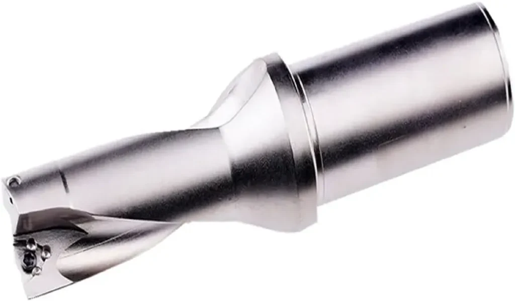
When machining deep holes with a length-to-diameter ratio greater than 5, internal cooling drilling technology should be used. Internal cooling drill bits are constructed from a single piece of carbide, similar to the helical structure of a standard twist drill. Cutting fluid is supplied to the cutting edge through an internal helical cavity and is discharged from the hole along with the chips.
For deep holes with a diameter less than 30mm, the DF machining system can be selected; for larger diameter holes, the BTA machining system can be used.
Key points for machining thin-walled parts
When machining thin-walled titanium alloy parts, the following countermeasures should be considered:
- Increase the number of heat treatment processes to eliminate work hardening and reduce stress deformation.
- Adopt a process route that first machines the inner hole, then uses an inner hole mandrel for positioning and turning the outer diameter.
- During outer diameter turning, add a hardened steel mandrel inside the hole to enhance the rigidity of the part and prevent deformation caused by chatter.
Laminated material processing
When machining carbon fiber composites and titanium alloy laminates, optimizing the chisel edge structure is particularly important. Studies have shown that an optimized chisel edge structure can significantly reduce axial cutting forces and torque, thereby improving drilling quality.
Real-world case studies and results verification
Case 1: Drilling Titanium Alloy Parts for an Aerospace Manufacturing Company
TC4 titanium alloy workpieces were machined using a molybdenum high-speed steel drill bit. The drill bit diameter was 6.35 mm, and the hole depth was 12.7 mm. Selected parameters: cutting speed 11.6 m/min, feed rate 0.127 mm/r, emulsion cooling.
Results: Each drill bit could machine 260 holes (wear standard 0.38 mm), significantly improving machining efficiency.
Case 2: Repairing Thin-Walled Titanium Alloy Structures in Aircraft
In drilling anti-cracking holes for aircraft titanium alloy skin, an S-type chisel-edge high-speed steel drill bit was used, coupled with micro-oil mist spray lubrication. Results showed that compared to a standard straight chisel-edge drill bit, the S-type chisel-edge drill bit reduced the drilling axial force by 28% and the hole roundness error by 58.9%.
Case Study 3: Machining of Deep Blind Holes in Iron Core Bushings
Deep blind holes (length-to-diameter ratio close to 20) in TC4 titanium alloy were machined using internal cooling drilling technology at a spindle speed of 1500 r/min, a feed rate of 0.03 mm/r, and a cooling pressure of 6 MPa. Results: Machining time was reduced from 40 minutes/piece to 6 minutes/piece, increasing efficiency by nearly 7 times. The borehole surface roughness reached Ra0.8, straightness was between 0.01-0.019 mm, and the drill bit life allowed for machining over 80 pieces.
Future development trends
With the increasing maturity of titanium alloy processing technology and continuous improvements in processing equipment and cutting tools, stable processing of ultra-large structural components and precision complex parts has now been achieved. In the future, titanium alloy processing technology will develop in the following directions:
- High Performance: Developing alloys with higher operating temperatures, higher specific strength, higher specific modulus, and better corrosion and wear resistance.
- Low Cost: Developing alloys containing little or no precious metal elements and adding inexpensive elements such as iron, oxygen, and nitrogen.
- New Technologies: Adopting new processing technologies, such as cold forming technology, to improve the production efficiency, yield, and performance of titanium alloys.
- Intelligent Processing: Using advanced computer technology to simulate the workpiece deformation process and predict the evolution of the metal’s microstructure.
Conclusion
Machining titanium alloys is not a simple matter of tool selection, but a systemic engineering project. From tool material and geometry to cutting parameters and cooling methods, every aspect requires careful design. By using YG-type cemented carbide, optimizing drill geometry, innovating chisel edge structures, and employing scientific machining parameters, it is entirely possible to overcome the challenges of drilling titanium alloys, improving production efficiency and product quality.
This article aims to provide practical assistance in solving real-world problems encountered in titanium alloy machining. Correct tool design combined with scientific machining parameters will increase your titanium alloy machining efficiency by over 30% and extend tool life by over 50%. If you have specific machining scenarios to discuss, please leave a comment in the comment section to exchange ideas or contact us.
Specific parameters should be fine-tuned according to actual conditions.


