헤비 및 준헤비 가공에는 해당 작업에 맞게 설계된 칩 브레이커가 필요합니다. 넓은 칩 브레이커는 넓은 절삭 깊이와 높은 이송량에서 칩 제어를 최적화합니다. 평평한 네거티브 랜드 설계로 절삭날 강도가 극대화됩니다. 반대로 정삭 작업에서는 칩 브레이커가 작아지면 절삭력이 감소하여 칩 브레이킹이 용이해집니다. 정삭 작업에서는 포지티브 랜드와 작은 에지 호닝으로 절삭날 선명도를 우선시합니다. CNMM 인서트는 황삭 가공에 탁월합니다.
CNMM 인서트 도구 홀더
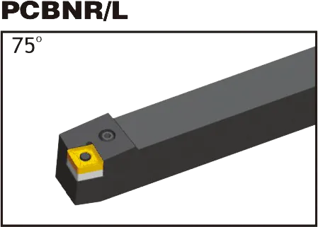
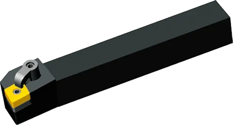
MCLNR/L
CNMM 삽입 소개
1. 치수
모양: 포함 각도가 80도인 마름모꼴(다이아몬드)입니다.
클리어런스 각도: 음수(일반적으로 -5 ~ -7도 범위).
관용: 중간(‘M’)이 일반적이지만 특수한 요구 사항에 따라 다른 허용 오차가 존재할 수 있습니다.
각인된 원(IC): 전체 인서트 크기를 결정합니다(일반: 12.7mm, 16mm).
두께: 임팩트 강도 및 절삭날 수(공통: 4.76mm, 6.35mm).
코너 반경: 강도와 표면 마감에 영향을 줍니다(공통: 0.4mm, 0.8mm, 1.2mm).
2. 칩브레이커 지오메트리
매우 중요합니다: 칩 브레이커는 칩이 형성되고 부서지는 방식을 형성하여 효율적인 칩 흐름, 공구 보호 및 공작물 마감을 보장합니다.
제조업체별: 칩브레이커 지정은 CNMM 코드(“MM”)로 코드화되어 있습니다. 자세한 내용은 제조업체 카탈로그를 참조하세요.
작업과 일치합니다: 생각해 보세요:
공작물 소재
컷 깊이(라이트 대 헤비)
원하는 마무리
3. 구멍 구성
중앙 구멍: 툴 홀더에 안전하게 고정합니다.
구멍이 없습니다: 다른 클램핑 메커니즘에 의존하세요.
툴 홀더 호환성: 인서트의 구멍 구성을 공구 홀더와 일치시키는 데 필수적입니다.
4. 코팅 및 기판
코팅: 일반적인 유형으로는 TiN, TiAlN, CVD, PVD가 있습니다. 각기 다른 내마모성, 열적 특성, 다양한 소재에 대한 적합성을 제공합니다.
서브스트레이트: 코팅이 적용되는 베이스 카바이드 소재입니다. 구성이 다양하여 인성 대 내마모성의 균형을 제공합니다.
애플리케이션별: 최적의 성능과 공구 수명을 위해서는 올바른 등급을 선택하는 것이 중요합니다.