
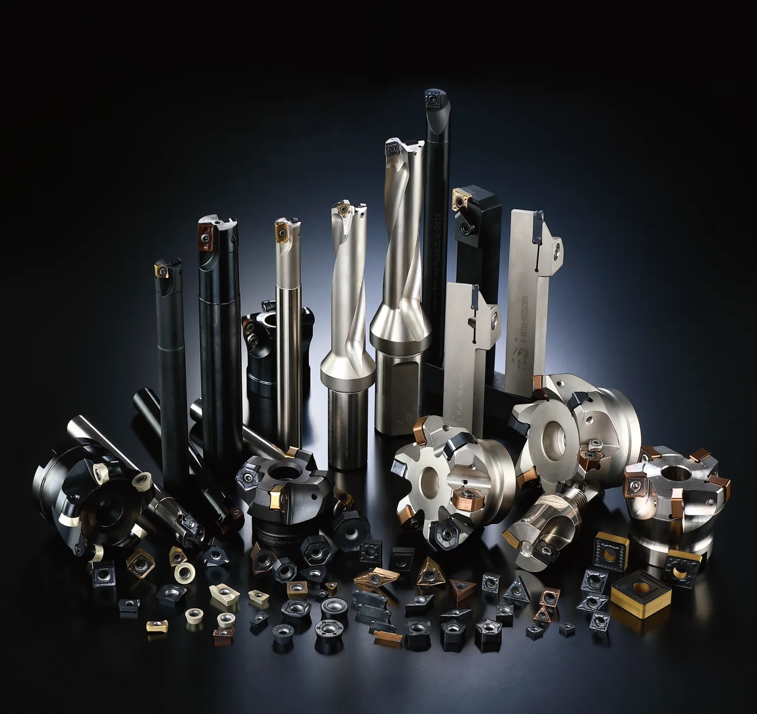
핵심 CNC 공구 관련 요구 사항을 모두 충족해 드리는 단일 공급업체
가공 공정에 따라 제품군을 선택하십시오. 초경 인서트는 여전히 주요 제품군으로 자리 잡고 있으며, 공구 홀더, 밀링 커터, 엔드밀 및 구멍 가공 공구 역시 각각 뚜렷한 진입점을 가지고 있습니다.
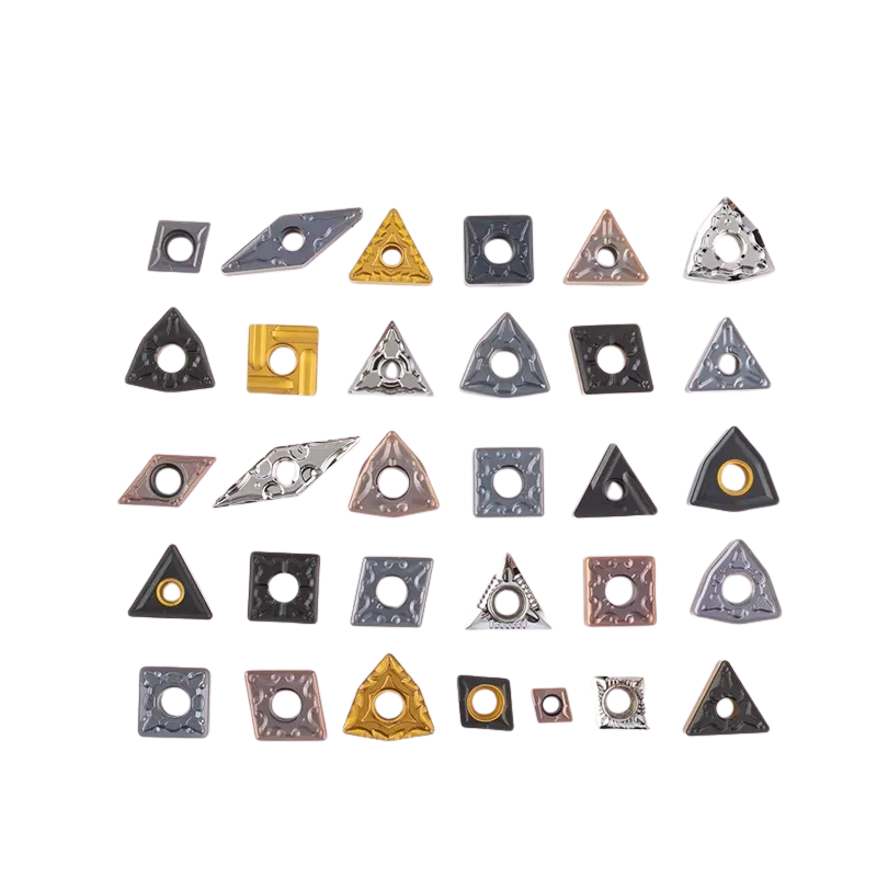
초경 인서트
재질 및 칩 브레이커 선택이 가능한 선삭, 밀링, 나사 가공, 홈 가공 및 드릴링 인서트.
카바이드 인서트 보기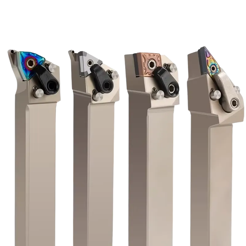
선삭 공구 홀더
외부 홀더, 보링 바, 나사 가공 홀더, 홈 가공 홀더 및 절단 시스템.
공구 홀더 보기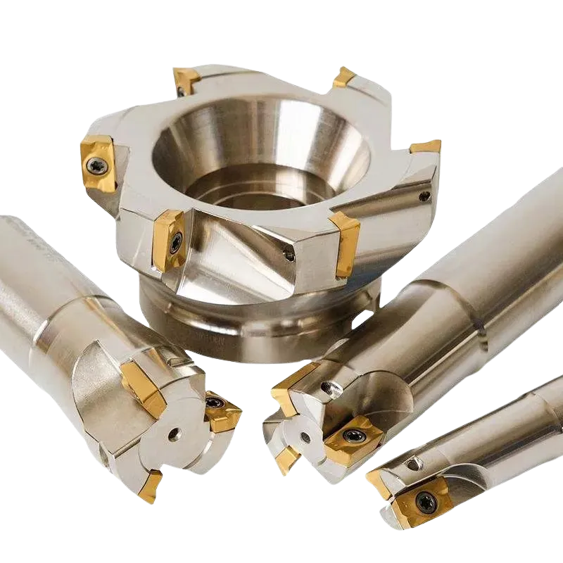
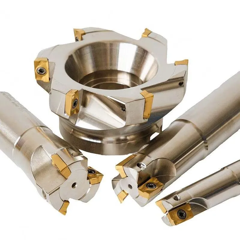
밀링 인서트 및 커터
면 밀링, 숄더 밀링, 프로파일링 및 황삭 밀링용 인서트 및 커터 솔루션.
밀링 공구 보기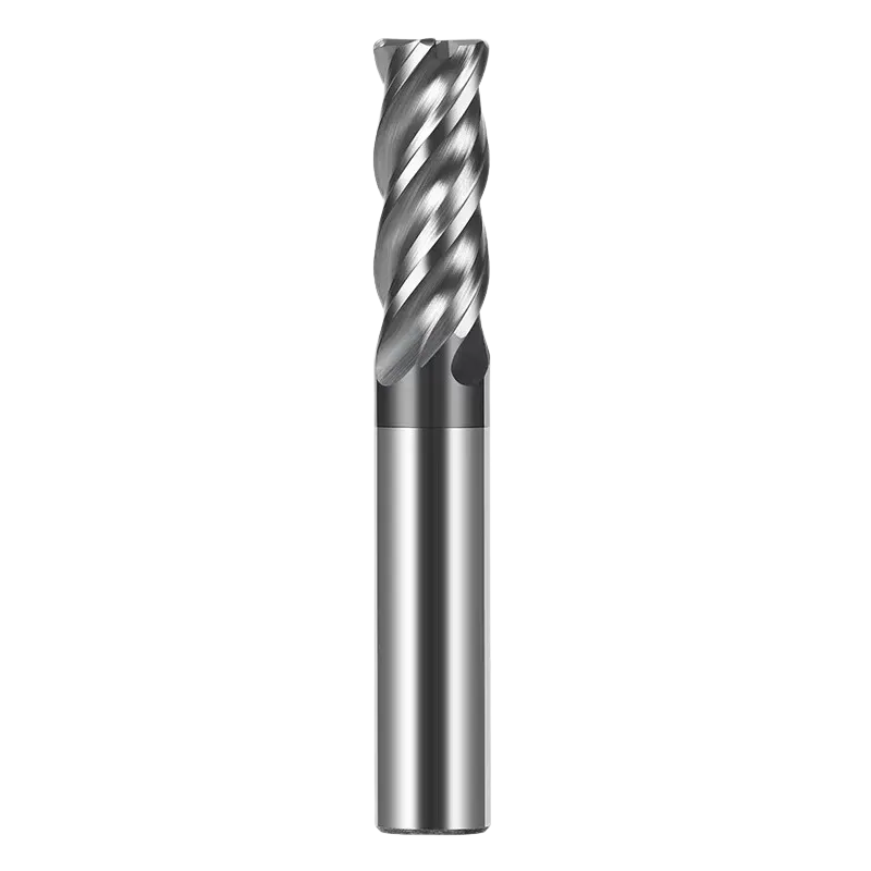
솔리드 카바이드 엔드밀
사각형, 볼 노즈, 코너 반경, 황삭, 롱 리치 및 소재별 엔드밀.
엔드밀 보기
선반 절삭 공구
교체형 드릴 비트, U-드릴 시스템 및 용도별 드릴링 공구 솔루션.
홀 제작 도구 보기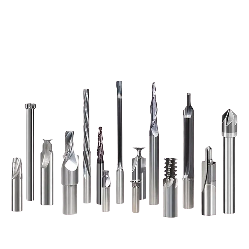
맞춤형 절삭 공구
도면 기반 삽입 부품, 성형 공구, 특수 프로파일, 맞춤형 엔드밀, 마킹 및 포장.
맞춤형 공구 보기가공 공정에 적합한 공구 선택
가공 방식에 따라 필요한 공구 시스템도 달라집니다. 먼저 공정을 파악한 다음, 공작물 재질, 공구 코드, 치수, 기계의 강성 및 생산 목표를 확인하십시오.
초경 인서트는 여전히 ONMY의 핵심 제품군으로 자리 잡고 있습니다
홈페이지에는 전체 공구 제품군이 소개되어 있으며, 특히 초경 인서트 카테고리에는 선삭 인서트, 밀링 인서트, 재종, 칩 브레이커 및 이에 상응하는 공구 코드를 찾는 구매자들을 위해 별도로 눈에 잘 띄는 항목이 마련되어 있습니다.
도면, 시제품 공구 또는 가공 관련 문제 보내기
카탈로그에 수록된 공구가 적합하지 않은 경우, ONMY는 실제 공작물과 가공 조건을 바탕으로 비표준 인서트, 맞춤형 프로파일, 특수 엔드밀 및 특정 용도에 맞는 공구를 검토해 드릴 수 있습니다.
기술 중심의 B2B 공구 문의를 위해 구축되었습니다
홈페이지는 구매자가 귀사의 전체 제품 라인업을 빠르게 파악하고, 적합한 제품 경로를 확인하며, 유용한 견적서를 작성하는 데 필요한 충분한 정보를 얻을 수 있도록 도와야 합니다.
전체 제품 범위
초경 인서트, 홀더, 밀링 커터, 솔리드 초경 엔드밀, 구멍 가공 공구 및 맞춤형 공구.
교체 및 조달
대안을 평가할 때는 ISO 코드, 현재 공급업체 코드, 도면 또는 샘플 공구를 기준으로 삼으십시오.
맞춤형 엔지니어링 요구 사항
치수, 형상, 도달 범위, 반경, 코팅, 재질 및 운영상의 제약 사항을 검토하십시오.
유통업체 및 OEM 지원
재공급, 제품 표시, 라벨, 포장 및 제품 라인 개발에 대해 논의하십시오.
가공이 필요한 부품을 알려주세요
유용한 공구 문의에는 제품명 이상의 정보가 포함되어야 합니다. 팀이 올바른 공구 방향을 검토할 수 있도록 이용 가능한 기술 정보를 보내 주시기 바랍니다.
공구 제작 요청 보내기
아래 양식은 WPForms 양식 ID 14에 의해 표시됩니다.
