CNC超硬インサートのワンストップメーカー

エンドミルとフェイスミルの比較

Optimizing Carbide End Mill Cutting Parameters: A Comprehensive Guide

In the world of precision machining, 超硬エンドミル have become indispensable tools for professionals seeking superior performance and efficiency. Whether you’re a seasoned machinist or just starting in the field, understanding and optimizing carbide end mill cutting parameters is crucial for achieving high-quality results and extending tool life. In this comprehensive guide, we’ll delve into the intricacies of carbide end mill feeds and speeds, explore carbide end mill RPM charts, and provide you with the knowledge to maximize your machining efficiency.

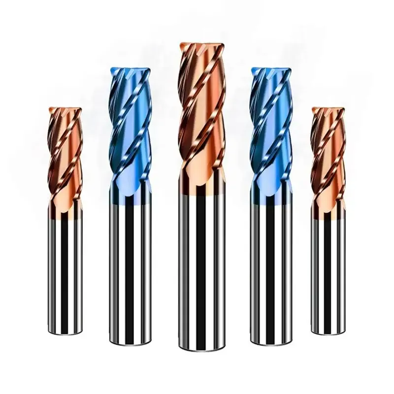
custom end mills

Ⅰ. Understanding Carbide End Mills

Before we dive into cutting parameters, let’s first understand what carbide end mills are and why they’re so popular in modern machining.

A. Definition and Composition

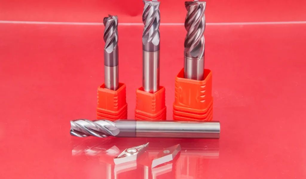
Carbide end mills are rotary cutting tools made from tungsten carbide, a composite material known for its exceptional hardness and wear resistance. These tools are designed to remove material from a workpiece through a combination of rotation and lateral movement.

B. Types of Carbide End Mills

There are various types of carbide end mills available, including:

  1. Flat end mills
  2. Ball nose end mills
  3. Corner radius end mills
  4. Tapered end mills
  5. Roughing end mills

Each type is designed for specific applications and cutting strategies.

C. Advantages Over Other Cutting Tools

Carbide end mills offer several advantages over their high-speed steel (HSS) counterparts:

  1. Higher hardness and wear resistance
  2. Ability to maintain sharp cutting edges for longer periods
  3. Capability to machine at higher speeds and feeds
  4. Improved thermal stability during high-speed operations

II. Key Cutting Parameters for Carbide End Mills

To achieve optimal performance with carbide end mills, it’s essential to understand and control the following cutting parameters:

china end mill

A. Cutting Speed

Cutting speed, measured in surface feet per minute (SFM) or meters per minute (m/min), refers to the speed at which the cutting edge of the tool moves relative to the workpiece. It’s a critical factor in determining the tool’s performance and life.

B. Feed Rate

Feed rate is the speed at which the tool advances into the workpiece. It’s typically measured in inches per minute (IPM) or millimeters per minute (mm/min). The feed rate directly affects the chip load, which is the amount of material removed by each cutting edge per revolution.

C. Depth of Cut

Depth of cut (DOC) is the distance the tool penetrates into the workpiece. It can be categorized as axial depth of cut (along the tool’s axis) and radial depth of cut (perpendicular to the tool’s axis).

D. Width of Cut

Width of cut, also known as stepover, is the distance the tool moves laterally between passes. It’s often expressed as a percentage of the tool’s diameter.

E. Coolant Application

Proper coolant application is crucial for heat dissipation, chip evacuation, and extending tool life. The type of coolant and its delivery method can significantly impact the cutting process.

III. Carbide End Mill Feeds and Speeds

Optimizing feeds and speeds is crucial for achieving the best results with 超硬エンドミル. Let’s explore this topic in detail:

Carbide End Mill Cutting Parameters
湿式ミリングと乾式ミリング

A. Importance of Proper Feeds and Speeds Correct feeds and speeds ensure:

  1. Optimal chip formation and evacuation
  2. Reduced tool wear and extended tool life
  3. Improved surface finish
  4. Enhanced machining efficiency

B. Factors Affecting Feeds and Speeds

Several factors influence the selection of appropriate feeds and speeds:

  1. Workpiece material properties
  2. Tool diameter and number of flutes
  3. Depth and width of cut
  4. マシンの機能
  5. Cutting strategy (roughing vs. finishing)

C. Calculating Optimal Feeds and Speeds

To calculate the optimal spindle speed (RPM) and feed rate, use the following formulas:

RPM = (Cutting Speed × 3.82) ÷ Tool Diameter Feed Rate = RPM × Feed per Tooth × Number of Flutes

D. Common Mistakes to Avoid

  1. Running tools too fast or too slow
  2. Incorrect chip load calculation
  3. Neglecting the impact of tool coating on cutting parameters
  4. Failing to adjust parameters for different materials

IV. Carbide End Mill RPM Chart

Understanding and utilizing RPM charts can greatly simplify the process of selecting appropriate cutting speeds for various materials.

A. Understanding RPM in Machining

RPM (Revolutions Per Minute) represents the number of complete rotations a tool makes in one minute. It’s directly related to the cutting speed and tool diameter.

B. Factors Influencing RPM Selection

  1. Tool diameter
  2. Workpiece material
  3. Desired cutting speed
  4. マシンの機能

C. Sample RPM Chart for Various Materials

Here’s a simplified RPM chart for a 1/2carbide end mill:

MaterialCutting Speed (SFM)回転数
Aluminum600-10004600-7600
Mild Steel250-4001900-3000
Stainless Steel100-3007600-2300
Titanium50-150380-1150

Note: Always consult your tool manufacturer’s recommendations for specific cutting parameters.

D. How to Use an RPM Chart Effectively

  1. Identify the workpiece material
  2. Select the appropriate cutting speed range
  3. Use the formula or chart to determine the RPM
  4. Adjust based on your specific tool and machine capabilities

V. Optimizing Cutting Parameters for Different Materials

Different materials require specific cutting parameters for optimal results. Let’s explore some common materials and their ideal cutting conditions:

Carbide End Mill Cutting Parameters
HSM

A. Aluminum

  1. High cutting speeds (600-1000 SFM)
  2. Higher feed rates due to material softness
  3. Use of coolant or minimum quantity lubrication (MQL)

B. Steel

  1. Moderate cutting speeds (250-400 SFM for mild steel)
  2. Adjust feed rates based on hardness
  3. Proper chip control is crucial

C. Stainless Steel

  1. Lower cutting speeds (100-300 SFM)
  2. Reduced feed rates to manage heat generation
  3. Use of high-pressure coolant for chip evacuation

D. Titanium

  1. Very low cutting speeds (50-150 SFM)
  2. Light cuts with high feed rates
  3. Abundant coolant to manage heat

E. Plastics and Composites

  1. Vary speeds based on specific material properties
  2. Use sharp tools to prevent melting or delamination
  3. Consider dry cutting or air blast cooling

VI. Advanced Techniques for Carbide End Mill Performance

To push the boundaries of carbide end mill performance, consider these advanced techniques:

A. High-Speed Machining (HSM)

  1. Utilizes higher cutting speeds and feed rates
  2. Reduces cutting forces and heat generation
  3. Requires specialized tooling and machine capabilities

B. Trochoidal Milling

  1. Employs a circular tool path with a small radial depth of cut
  2. Reduces tool engagement and extends tool life
  3. Ideal for slotting and pocket milling operations

C. Climb Milling vs. Conventional Milling

  1. Climb milling: Tool rotation is in the same direction as the feed
  2. Conventional milling: Tool rotation opposes the feed direction
  3. Climb milling generally produces better surface finish and tool life

VII. Troubleshooting Common Issues

Even with optimal cutting parameters, issues may arise. Here’s how to address common problems:

A. Tool Wear and Breakage

  1. Causes: Excessive cutting speed, inadequate cooling, improper chip evacuation
  2. Solutions: Adjust cutting parameters, improve coolant delivery, use tools with chipbreaker geometry

B. Poor Surface Finish

  1. Causes: Incorrect feed rate, tool deflection, worn cutting edges
  2. Solutions: Optimize feed rate, use shorter tools or add support, replace worn tools

C. Chatter and Vibration

  1. Causes: Excessive cutting forces, inadequate tool holding, resonance
  2. Solutions: Reduce depth of cut, improve tool holding, adjust spindle speed

D. Chip Control Problems

  1. Causes: Inadequate chip evacuation, incorrect cutting parameters
  2. Solutions: Optimize coolant delivery, adjust feed rate and depth of cut, use tools with chipbreaker geometry

VIII. Best Practices for Extending Carbide End Mill Life

Implementing these best practices can significantly extend the life of your carbide end mills:

A. Proper Tool Storage and Handling

  1. Store tools in a clean, dry environment
  2. Use protective cases or racks to prevent damage
  3. Handle tools carefully to avoid chipping cutting edges

B. Regular Tool Inspection and Maintenance

  1. Inspect tools for wear and damage before each use
  2. Rotate or index cutting edges when wear is detected
  3. Regrind tools when necessary, following manufacturer guidelines

C. Optimal Cutting Fluid Selection and Application

  1. Choose the right cutting fluid for your application
  2. Ensure proper concentration and filtration
  3. Maintain consistent and adequate fluid delivery

結論

Mastering carbide end mill cutting parameters is essential for achieving optimal machining results and maximizing tool life. By understanding the intricacies of feeds and speeds, utilizing RPM charts, and applying advanced techniques, you can significantly improve your machining efficiency and quality.

Remember that the world of machining is constantly evolving, with new tools, materials, and techniques emerging regularly. Stay informed about the latest developments in carbide end mill technology and continue to experiment and refine your processes.

As you apply the knowledge gained from this guide, you’ll find that optimizing your carbide end mill cutting parameters not only improves your machining results but also contributes to increased productivity and reduced operational costs. Keep pushing the boundaries of what’s possible with these versatile and powerful cutting tools.

これを共有:

コメントを残す

あなたのメールアドレスが公開されることはありません。 必須フィールドは、マークされています *

トップにスクロールします
× どんな御用でしょうか?