Erreurs d'usinage des vis à os : Pourquoi le tourbillonnement du filetage La largeur de l'insert n'est jamais égale au pas du filetage

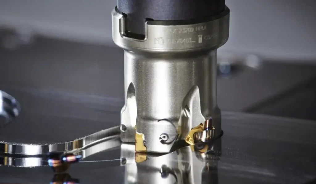
Dans le monde de haute précision de la fabrication de dispositifs médicaux, en particulier lors du tournage CNC et du tourbillonnage de vis à os en titane, la conception d'inserts de filetage personnalisés est absolument cruciale. Cependant, une seule erreur de dessin, apparemment mineure, sur l'impression d'une plaquette personnalisée peut entraîner une grande confusion, des maux de tête en matière de programmation et des pièces mises au rebut dans l'atelier.
Un piège géométrique courant, mais dangereux, dans lequel tombent de nombreux ingénieurs et dessinateurs consiste à confondre les paramètres de la pièce à usiner avec les dimensions physiques de l'outil. Plus précisément, ils assimilent à tort les paramètres de la pièce aux dimensions physiques de l'outil. “Pas de fil” directement à la largeur de base physique du profil de l'outil de coupe.
Grâce à une correction de dessin dans le monde réel et à une déduction géométrique CAO rigoureuse, cet article exposera les raisons pour lesquelles cette hypothèse est fondamentalement erronée. Nous allons décomposer la relation mathématique exacte entre le profil de l'outil et le pas de la pièce, prouvant ainsi une règle d'or dans l'usinage CNC : Le pas du filet est généré par la vitesse d'avance de la machine-outil et n'est pas bloqué par la largeur physique de la plaquette de coupe.
Étude de cas : Un dessin d'insertion non standard plein de contradictions géométriques
Imaginez que vous receviez un plan pour un insert de tourbillonnage sur mesure, spécialement conçu pour usiner des vis à os en titane. À première vue, les exigences techniques - angles, rayons et profondeurs - semblent parfaitement standard. Cependant, une inspection plus approfondie du “Détail A” (la vue agrandie du profil de coupe) révèle une erreur de dessin critique qui pourrait facilement saboter l'ensemble de la production.
Sur ce dessin particulier, le dessinateur a placé une dimension de 1.75 ±0.01 directement à la base du profil à dent unique de l'insert. Ce chiffre n'est pas arbitraire ; 1,75 mm est exactement le pas requis pour la vis à os. La logique sous-jacente est un piège courant : le concepteur a supposé que, puisque l'outil coupe un filet avec un pas de 1,75 mm, l'outil de coupe lui-même doit avoir une largeur de base physique de 1,75 mm.

Pourquoi cette dimension est-elle un piège fatal pour l'usinage CNC ?
Cette hypothèse découle d'une confusion classique entre les notions de géométrie statique de l'outil et le le mouvement dynamique de la machine. Si un fabricant d'outillage suit aveuglément ce dessin et rectifie la plaquette à une largeur de base de 1,75 mm, l'atelier devra faire face à de graves conséquences :
- Un profil de coupe surdimensionné : L'outil devient physiquement disproportionné. Pour un profil en V ou un filet trapézoïdal modifié, la largeur de la coupe s'étend dynamiquement du sommet plat (racine du filet) au diamètre extérieur. Forcer la largeur de base à être de 1,75 mm fausse les angles de coupe requis et crée une arête de coupe excessivement large.
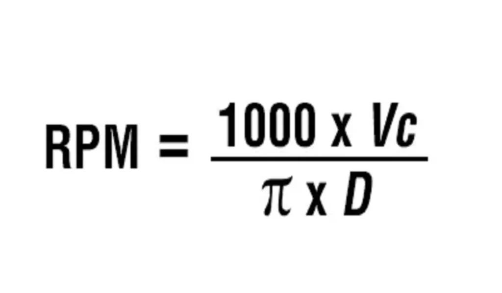
- Surcoupe catastrophique (The Vanishing Crest) : Dans le tourbillonnage ou le tournage CNC, le pas de filetage est généré par l'axe Z de la machine qui avance exactement de 1,75 mm par tour de broche (
F1.75). Si l'outil lui-même est artificiellement élargi à 1,75 mm à sa base, la largeur totale de la rainure qu'il creuse sur la surface de la vis dépassera de loin le pas de 1,75 mm. Au fur et à mesure des passages de la machine, l'outil surdimensionné se chevauchera inévitablement et entamera le matériau qui était censé rester en place. - Pièces mises au rebut : Le résultat immédiat de ce chevauchement est l'oblitération complète de la crête du filetage (la partie supérieure plate du filetage de la vis à os). La crête étant essentielle à la force de préhension et à l'intégrité structurelle de la vis à l'intérieur du corps humain, le produit final ne sera pas un dispositif médical fonctionnel, mais une tige de titane abîmée et trop usinée.
Le calcul intensif : Quelle est la quantité de matière qu'une seule dent “sculpte” en réalité ?
Pour comprendre pourquoi une dimension de base de 1,75 mm est une erreur catastrophique, nous devons séparer les exigences de la pièce à usiner des propriétés physiques inhérentes à l'outil. Éliminons la confusion et examinons strictement la géométrie de la plaquette de coupe.
En fonction du profil de filetage requis, les paramètres corrects et non modifiables de la plaquette sont les suivants :
- Largeur du plateau supérieur (qui forme la racine du filet de la vis) : 1,0 mm
- Profondeur de coupe : 1,05 mm
- Angle du flanc gauche : 5°
- Angle du flanc droit : 25°
Déduction trigonométrique de la largeur d'ouverture de la surface
Lorsque cet insert plonge dans le stock de titane, il ne se contente pas de découper une fente droite de 1,00 mm. Comme les flancs sont inclinés, la rainure en forme de V s'élargit progressivement de la racine (point le plus profond) jusqu'au diamètre extérieur (surface) de la vis d'ostéosynthèse.
Nous pouvons déterminer la largeur maximale exacte de la matière enlevée par une seule dent en un seul passage à l'aide de la trigonométrie de base :
Surface totale Largeur d'ouverture = Largeur du plat supérieur + Extension du côté gauche + Extension du côté droit
- Largeur du plateau supérieur : 1,0 mm
- Expansion du côté gauche : 1,05*tan(5°)≈0,092mm
- Expansion du côté droit : 1,05*tan(25°)≈0,49mm
Mettons la formule au point :
1.0+1.05*tan(5°)+1.05**tan(25°)=1.581mm
La vérité géométrique : Lorsque cet insert spécifique atteint sa profondeur de coupe maximale de $1.05\text{ mm}$, la largeur totale de la rainure qu'il creuse sur la surface extérieure de la vis osseuse est d'exactement 1,581 mm.
C'est le cas pas de sculpter un espace de 1,75 mm. Le chiffre 1,581 mm correspond à l'empreinte physique définitive de l'outil. Forcer la dimension de base de l'outil à être de 1,75 mm sur l'impression n'est pas seulement sans fondement mathématique, mais cela garantit aussi physiquement la destruction du profil du filet pendant l'usinage.
Voici la suite de l'article, qui amène la preuve géométrique à sa conclusion logique et pratique.
La vérité révélée : Angle d'inclinaison et profil par le biais d'une coupe transversale CAO

(Note pour la publication : Insérez ici votre image corrigée de coupe transversale CAO verte pour ancrer visuellement cette explication).
Pour dissiper le brouillard et établir une norme infaillible pour votre atelier, nous devons examiner la géométrie sous un angle différent - littéralement. Une coupe transversale CAO 2D de la vis à os usinée illustre parfaitement la différence critique entre l'espace que l'outil supprime et la trajectoire que la machine emprunte.
En cartographiant le profil de l'outil directement sur la pièce à usiner, nous pouvons clairement isoler trois dimensions distinctes qui ne doivent jamais être confondues :
- La largeur de la racine (1.000 mm) : Cela correspond directement au sommet plat de la plaquette. Il dicte la largeur exacte de la vallée du filet (la partie la plus profonde de la coupe). Il s'agit d'une propriété rigide et statique de l'outillage.
- La largeur de l'ouverture de la surface (1,581 mm) : Comme calculé ci-dessus, il s'agit de l'empreinte totale de la coupe au niveau du diamètre extérieur de la vis. Il s'agit d'une dimension dynamique déterminée conjointement par la largeur du plat de l'outil, sa profondeur de coupe et l'expansion vers l'extérieur de ses angles de flanc.
- Le pas de vis réel (1,750 mm) : Il s'agit d'un paramètre d'usinage absolu. Il représente la distance exacte à laquelle l'axe Z de la machine CNC avance par tour de broche.
L'erreur fondamentale du plan initial consistait à réduire le mouvement requis de la machine (1,750 mm) à l'empreinte physique de l'outil (1,581 mm).
Où est passé le 0,169 mm manquant ? L'écusson vital
Si la machine CNC avance de 1,750 mm à chaque rotation, mais que la plaquette de coupe ne creuse qu'un espace de 1,581 mm, il y a un écart mathématique évident :
$$1.750\text{ mm (Pas)} - 1.581\text{ mm (Largeur de coupe)} = 0.169\text{ mm}$$
Qu'advient-il de ces 0,169 mm ? Il s'agit du titane non touché qui reste entre deux passes de coupe consécutives. Dans la terminologie du filetage, ce matériau restant est le Crête du fil.
Pour les implants médicaux tels que les vis à os en titane, cette crête plate n'est pas un détail après coup, c'est une caractéristique essentielle de la conception. Une crête bien définie d'environ 0,17 mm empêche le fil de se transformer en une arête tranchante (qui pourrait trancher l'os au lieu de s'y ancrer) et garantit la résistance à l'arrachement nécessaire à la sécurité du patient.
Si le fabricant d'outils avait suivi le dessin original et défectueux et rectifié la base de l'outil à 1,750 mm, la largeur de coupe aurait été égale (ou supérieure) au pas, oblitérant complètement cette crête de 0,169 mm et entraînant le rejet immédiat de la pièce.
Conseils d'experts pour l'approvisionnement en outillage et les programmeurs CNC : comment éviter le piège du profil de tangage
L'étude de cas ci-dessus met en évidence une vulnérabilité critique dans la chaîne d'approvisionnement de la fabrication : une mauvaise interprétation entre la conception de la pièce, l'ingénierie de l'outil et l'exécution dans l'atelier. Lors de la commande d'inserts de filetage non standard personnalisés - en particulier les outils à profil en V ou les outils trapézoïdaux modifiés utilisés dans le tourbillonnage - la prévention de ces pièges géométriques nécessite un audit rigoureux et une communication claire.
Voici les protocoles essentiels que tout spécialiste de l'approvisionnement en outillage et tout programmeur CNC devraient adopter :
Protocoles de vérification des plans pour les encarts non standard
- Découpler la pièce de l'outil : N'acceptez jamais une impression d'outil qui impose le mouvement dynamique de la machine (le pas) à une dimension physique statique de la plaquette de coupe. L'impression de l'outil doit définir strictement la géométrie inhérente de l'outil : Largeur du plat supérieur (racine), profondeur de coupe, angles des flancs et rayons des coins.
- Lancer le calcul de l'ouverture de la surface : Avant d'approuver un insert de tourbillonnage personnalisé, effectuez vous-même la vérification trigonométrique. Calculez la Surface totale Largeur d'ouverture en fonction de la profondeur et des angles. Si cette largeur calculée est égale ou supérieure au pas de filetage requis, vous détruirez inévitablement la crête du filet lors de l'usinage.
Meilleures pratiques en matière de communication avec les fournisseurs et de clarification technique
- Obliger à apposer des étiquettes “Référence uniquement” : Il est compréhensible que les concepteurs veuillent noter le pas cible sur le dessin de l'outillage pour le mettre en contexte. Toutefois, si le pas (par exemple, 1,75) apparaît sur l'impression, il est possible d'en tirer des conclusions. doit entre parenthèses
(1.75)ou explicitement étiquetés commeREF(Référence) ouNote : Pour l'usinage P1.75. Il ne doit jamais avoir de tolérance de fabrication (comme±0.01), car cela signale à tort au broyeur qu'il s'agit d'une dimension de contrôle physique difficile. - Demande de calques CAO pour les profils personnalisés : Ne vous fiez pas uniquement aux dessins d'outils statiques en 2D. Lorsque vous travaillez avec un fabricant d'outils pour des composants médicaux à fort enjeu, tels que des vis à os en titane, demandez une superposition CAO ou une coupe transversale simulée (comme l'image CAO verte montrée plus haut). La visualisation de l'outil engagé dans la pièce à la vitesse d'avance programmée est le seul moyen infaillible de garantir que la crête de filetage souhaitée sera préservée.
En mettant en œuvre ces contrôles simples, les équipes de fabrication peuvent éliminer les erreurs de surcoupe coûteuses, éviter la mise au rebut d'un stock de titane onéreux et s'assurer que chaque vis à os usinée respecte les tolérances exactes et vitales exigées par l'industrie médicale.
Résumé : Règles de base du pas de vis par rapport au profil de la plaquette
Lors de l'usinage de vis à os médicales, confondre la géométrie de l'outil de coupe avec le mouvement de la machine est une erreur coûteuse. Pour garantir la précision et éviter les pièces mises au rebut, il convient de se rappeler ces règles fondamentales :
- La largeur de l'outil détermine la racine : Le sommet plat de la plaquette de coupe est une dimension statique qui détermine exclusivement la largeur de la vallée (racine) du filet.
- L'alimentation de la machine détermine le pas : Le pas de vis réel est entièrement généré par l'avance de l'axe Z de la machine CNC par tour. Il n'est jamais bloqué par la largeur de base de l'outil.
- La géométrie détermine la largeur de coupe : La largeur réelle découpée à la surface de la pièce est déterminée de manière dynamique par la largeur du plat de l'outil, sa profondeur de coupe et l'expansion vers l'extérieur de ses angles de dépouille.
- Le reste forme la crête : Le sommet plat critique (crête) du filet est la différence mathématique entre le pas programmé de la machine et la largeur de coupe totale de la surface de l'outil.