Custom carbide end mills are precision-engineered cutting tools tailored to specific machining challenges, offering unmatched versatility for industries like aerospace, automotive, medical devices, and die/mold production. Unlike standard end mills, these are designed from the ground up to handle unique geometries, materials, and performance demands—such as complex contours in titanium alloys or high-volume roughing in hardened steels. By customizing factors like flute count, helix angles, and coatings, manufacturers can achieve superior precision, extended tool life (up to 2-3x longer than off-the-shelf options), more flexible production and delivery schedules, and lower overall costs through optimized material removal rates (MRR). This guide covers types, design considerations, the customization process, key manufacturers, and practical tips to help you integrate custom tools into your workflow.
When to Choose Custom End Mills

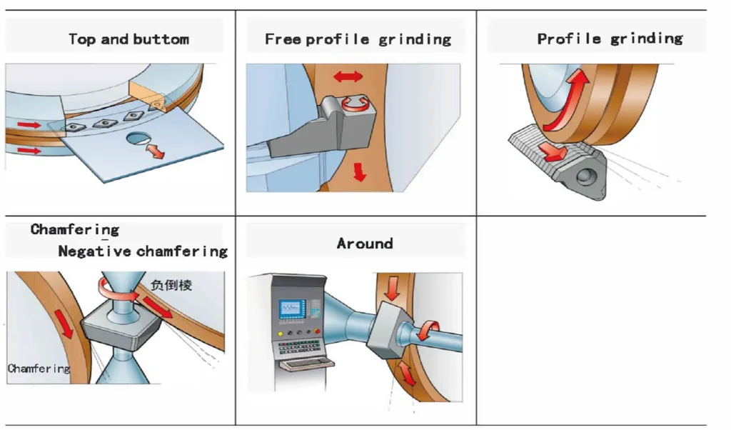
1. Unique Geometry or Complex Part Design
- When your part requires non-standard profiles, such as special radii, chamfers, tapered angles, or form tools.
- Complex 3D contours or features that standard end mills cannot achieve efficiently or precisely.
2. High-Volume Production — Improve Efficiency
- In mass production, a custom end mill can:
- Combine multiple machining steps into one tool.
- Reduce machining time and tool changes.
- Increase repeatability and consistency.
- Reduced cycle time can offset the higher initial cost.
3. Machining Difficult Materials
- For materials like titanium, Inconel, hardened steels, composites, or superalloys.
- Custom tools can be designed with:
- Specialized coatings,
- Edge prep,
- Flute geometry to reduce vibration and heat.
- Specialized coatings,
4. Longer Tool Life Requirements
- When tooling costs are high or downtime is expensive.
- Custom end mills can be optimized for:
- Better chip evacuation,
- Specific spindle speeds and feed rates,
- Increased durability.
5. Tight Tolerances or Superior Surface Finish
- Precision components in aerospace, medical, optics, or mold-making.
- Custom geometries provide higher accuracy and smoother finishes without secondary operations.
6. Special Machine or Setup Constraints
- If you’re using a unique CNC setup, limited tool holders, or short-reach spindles.
- Custom tools can be tailored for:
- Specific lengths,
- Shank sizes,
- Extended reach with reduced chatter.
⚖️ Custom vs. Standard End Mills — Quick Comparison

| Criteria | Standard End Mill | Custom End Mill |
|---|---|---|
| Availability | In stock, ready to use | Made to order, lead time required |
| Cost | Lower initial investment | Higher upfront cost |
| Design Flexibility | Limited to catalog geometry | Fully tailored to application |
| Performance Optimization | General-purpose | Optimized for material & process |
| Best for | Prototypes, low production | High-volume, complex, precision work |
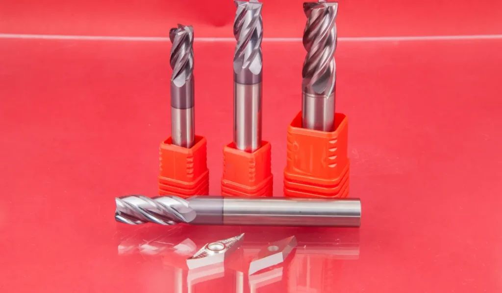
Types of Custom End Mills
Customization allows for hybrid designs combining features for targeted applications. Common types include:
| Type of Custom End Mill | Key Features | Typical Applications |
|---|---|---|
| Custom Profile/Form End Mills | Custom geometry for specific shapes (fillets, undercuts, grooves) | Mold & die making, complex contours in single pass |
| Tapered End Mills | Custom taper angles, optional ball or flat tips | Engraving, molds, deep angled walls |
| Corner Radius End Mills | Rounded corner edge instead of sharp | Higher tool strength, extended tool life, mold finishing |
| Corner Chamfer End Mills | Customized chamfer angle at edges | Deburring, edge preparation, improved durability |
| Bull Nose End Mills | Flat bottom with partial radius | 3D contouring, semi-finishing surfaces |
| Step / Multi-Diameter End Mills | Multiple cutting diameters in one tool | Combine drilling + milling, reduce tool changes |
| Ball Nose End Mills | Hemispherical tip, customizable radius | 3D surfaces, aerospace, turbine blades, die/mold cavities |
| Tapered Ball Nose End Mills | Combination of taper + ball tip | Deep 3D mold machining, engraving with strength |
| Extended Reach / Reduced Shank Mills | Long neck/reach, smaller shank, designed to reduce vibration | Deep cavities, interference avoidance, pocket milling |
| Material-Specific End Mills | Geometry & coatings designed for specific materials | Aluminum: high helix & polish; Titanium/Inconel: variable helix & coating; Hardened steel: corner radius & carbide |
| Coolant-Through End Mills | Internal coolant holes for direct cutting zone cooling | High-speed machining, deep pocketing, heat-sensitive materials |
| Roughing–Finishing Hybrid Mills | Serrated edges + smooth finishing section in one tool | High stock removal + fine surface finish in one pass |
| Thread Milling / Helical Custom Tools | Custom thread pitch, diameter, single/multi-tooth | Internal/external threads, helical grooves, pipe threads |
Key Design Considerations
Designing a custom end mill requires balancing performance, durability, and manufacturability. Focus on these five critical factors:
- Carbide Grade Selection: Match the cobalt binder content to the workpiece—higher cobalt (8-12%) for toughness in superalloys like Inconel; lower (4-6%) for hardness in cast irons. This ensures optimal wear resistance without brittleness.
- Helix Angle: Steeper angles (35-45°) for non-ferrous materials like aluminum to reduce forces and improve finishes; shallower (30-35°) for steels to handle heavier chips and resist deflection.
- Edge Preparation (Honing): Apply light chamfers or radii to eliminate micro-fractures from grinding, but avoid over-honing on stainless steels to prevent heat buildup and hardening.
- Differential Pitch: Uneven flute spacing (e.g., 4-flute with pitches of 85°/95°) to disrupt harmonic vibrations, reducing chatter in long-reach tools.
- Core Diameter: Thicker cores (60-70% of cutter diameter) for ferrous roughing to boost rigidity; slimmer for non-ferrous to allow deeper flutes and higher feeds.

Other parameters include flute length (up to 12″(300mm) for deep milling), neck diameter for clearance, and coatings like AlTiN for ferrous or DLC for gummy materials.
The Customization Process for End Mills
| Step | What Happens | Details & Key Considerations |
|---|---|---|
| 1. Requirement Analysis | Gather machining needs and application details | – Part drawing, 3D model, or sample provided- Material being machined (steel, titanium, aluminum, etc.)- Production volume and tolerance requirements |
| 2. Tool Design & Geometry Selection | Engineers develop tool geometry tailored to your needs | – Tool type (form, ball nose, step, taper, etc.)- Diameter, flute count, helix angle- Corner radius/chamfer, cutting length, shank size |
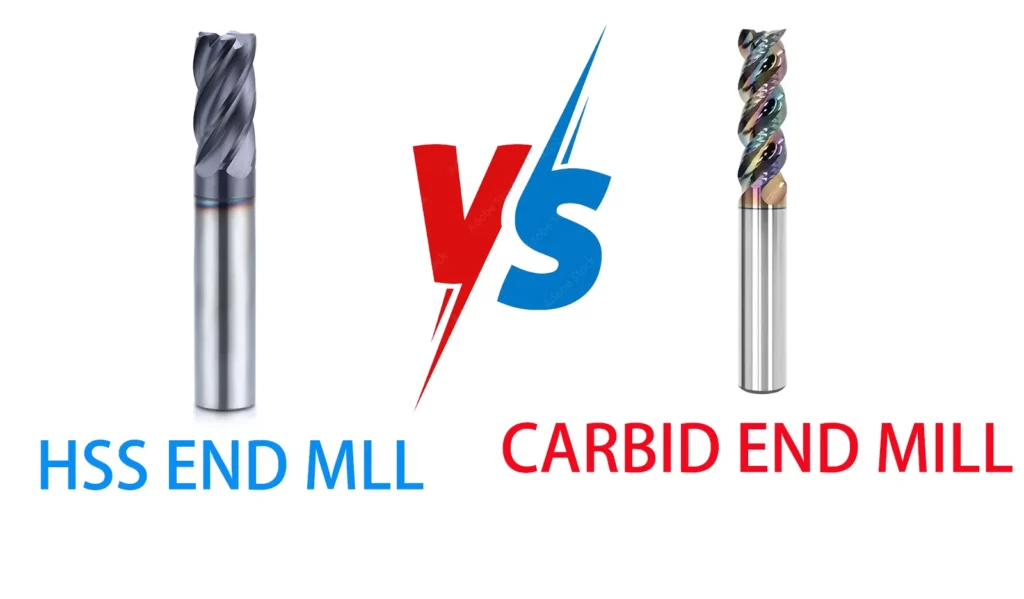
| 3. Material & Coating Selection | Choose base tool material and surface coating | – Tool material (Carbide, HSS, Cobalt, PCD, CBN)- Coating options (TiAlN, AlCrN, DLC, Diamond, etc.) depending on work material and speed- Edge prep (honing, polishing, chip breaker) |
| 4. CAD/CAM Modeling & Simulation | Create 3D model and test virtually | – Tool drawn in CAD software (SolidWorks, AutoCAD)- Simulated cutting paths in CAM to check tool strength, chip evacuation, heat behavior |
| 5. Manufacturing the Tool | Precision grinding and tool-making process | – CNC grinding machines create tool geometry- Quality steel/carbide rods are used- Coolant holes added if internal coolant design is required |
| 6. Coating Application (Optional) | Apply protective and performance-enhancing layer | – PVD, CVD, or CBN coating applied based on temperature and material requirements |
| 7. Inspection & Quality Testing | Dimension and performance verification | – 3D laser measurement, digital microscope inspection- Runout, concentricity, flute geometry, diameter accuracy checks |
| 8. Prototype Testing (Optional) | Trial cutting on actual material | – Performance evaluated: surface finish, tool wear, chatter, cutting forces- Adjust design if needed |
| 9. Mass Production & Delivery | Final batch manufacturing and shipping | – Tool serial numbers/labels- Packaging with technical data sheet or usage recommendations |
| 10. Feedback & Optimization | Improvement based on user feedback | – Cutting performance data reviewed- Adjustments made for future orders if necessary |
Leading Manufacturers and Suppliers
| Manufacturer | Specialties | Lead Time/Features | Contact |
|---|---|---|---|
| Harvey Tool | Solid carbide profiles, quickturn keyseats. | Instant quotes; up to 6 flutes. | harveytool.com |
| Fullerton Tool | High-performance end mills with coatings. | Build online; nanometer tolerances. | fullertontool.com |
| Speed Tiger | Trochoidal designs for HRC 65+ steels. | From sketches; AlTiBN coatings. | speedtigertools.com |
| Baucor | Tapered/dovetail mills in HSS/carbide. | 1-12″ lengths; FEA validation. | baucor.com |
| Exactaform | Differential pitch for chatter-free cuts. | Aerospace-grade; custom helix. | exactaform.com |
| Kodiak Cutting Tools | Versatile carbide selection for all materials. | Standard-to-custom hybrids. | kodiakcuttingtools.com |
Optimization Tips and Best Practices
- Start with Data: Log baseline performance from standard tools to quantify improvements (e.g., aim for 20% MRR increase).
- Material Matching: Use P/M/K/N/S/H groups for steels/non-ferrous/superalloys to guide grades.
- Testing Protocol: Ramp parameters conservatively—start at 70% recommended feeds/speeds; monitor via dynamometers for force spikes.
- Maintenance: Regrind at 60% wear; store in anti-corrosion sleeves.
- Trends to Watch: AI-driven designs for predictive wear and 3D-printed prototypes for rapid iteration.
Custom end mills can transform inefficient processes into high-precision operations, but success hinges on clear specs and manufacturer expertise. For your project, begin with a detailed inquiry to a trusted supplier—many offer free consultations. If you provide specifics (e.g., material or geometry), I can refine these recommendations further.