Канавочные вставки: Основные инструменты для прецизионной обработки
В мире металлообработки и ЧПУ-обработки плашки для пазов играют решающую роль в достижении точных и эффективных результатов. Эти универсальные режущие инструменты незаменимы для создания пазов, прорезей и других сложных элементов в заготовках. Независимо от того, являетесь ли вы опытным станочником или новичком в этой области, понимание принципа работы плашек для пазов необходимо для освоения различных операций обработки. В этом всеобъемлющем руководстве будут подробно рассмотрены тонкости пазовые вставки, изучая их типы, области применения и передовые методы, которые помогут вам оптимизировать процессы механической обработки.
Что такое канавочные вставки?
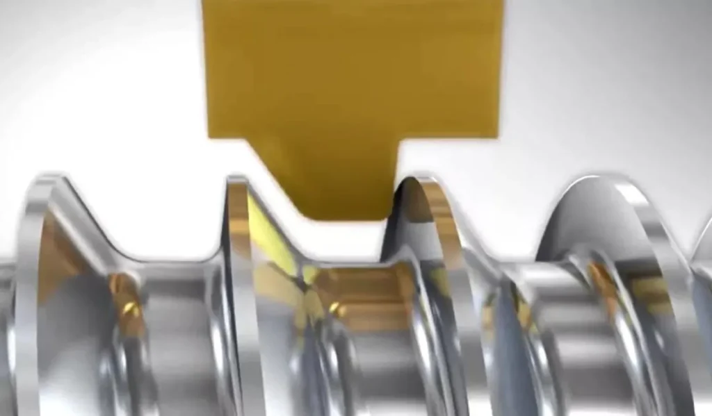
Режущие пластины это специализированные режущие инструменты, предназначенные для создания канавок, каналов или углублений в заготовке. Эти пластины обычно изготавливаются из твердых, износостойких материалов, таких как карбид, керамика или поликристаллический алмаз (PCD). Канавочные пластины используются в различных операциях обработки, включая точение, фрезерование и нарезание резьбы, для получения точных и последовательных профилей канавок.
Конструкция пластин для обработки канавок тщательно продумана, чтобы обеспечить баланс между эффективностью резания, контролем стружки и сроком службы инструмента. Большинство канавочных пластин имеют одну режущую кромку, что позволяет точно контролировать ширину и глубину канавки. Геометрия режущей кромки оптимизирована для снижения сил резания и улучшения отвода стружки, обеспечивая чистый и точный профиль канавки.
Типы канавочных пластин
Мир канавочных пластин очень разнообразен, в нем представлены различные типы, разработанные для удовлетворения конкретных требований к обработке. Давайте подробно рассмотрим основные категории:
1. Вставки для обработки канавок с ЧПУ
Пазовые пластины с ЧПУ специально разработаны для использования в станках с числовым программным управлением (ЧПУ). Эти пластины отличаются высокой точностью и повторяемостью, что делает их идеальными для крупносерийного производства. Вставки для обработки канавок с ЧПУ имеют различные формы и размеры, что позволяет использовать их для различных профилей канавок и параметров обработки.
Основные характеристики пазовых пластин с ЧПУ включают:
- Точные допуски на размеры для получения стабильных результатов
- Усовершенствованная конструкция стружколомателя для лучшего контроля стружки
- Совместимость с высокоскоростными операциями обработки
- Оптимизированная геометрия для снижения силы резания и увеличения срока службы инструмента
Пример применения: Пазовая пластина с ЧПУ может использоваться в автомобильной промышленности для создания точных канавок для поршневых колец в блоках двигателя, обеспечивая оптимальную герметичность и производительность.
2. Пластины для обработки канавок PCD
Пластины для обработки канавок из поликристаллического алмаза (PCD) - это режущий инструмент премиум-класса, известный своей исключительной твердостью и износостойкостью. Эти пластины особенно эффективны при обработке абразивных материалов, таких как алюминиевые сплавы, композиты и цветные металлы. Пластины для обработки канавок PCD обеспечивают длительный срок службы инструмента и превосходное качество обработки поверхности.
Преимущества пластин для обработки канавок PCD включают:
- Высочайшая твердость и износостойкость
- Отличная теплопроводность для отвода тепла
- Способность сохранять остроту режущей кромки в течение длительного времени
- Идеально подходит для крупносерийного производства деталей из цветных металлов
Пример применения: В аэрокосмической промышленности пластины для обработки канавок PCD могут использоваться для обработки канавок в алюминиевых деталях самолетов, где точность и качество поверхности имеют решающее значение.
3. Вставки для обработки торцевых канавок
Продольное рифление Пластины предназначены для создания канавок на торце или конце заготовки. Эти пластины обычно используются при токарной обработке для создания круглых канавок, гнезд для уплотнительных колец и других радиальных элементов. Пластины для торцевого нарезания канавок часто имеют специальную геометрию, обеспечивающую удаление стружки и минимизацию режущих усилий.
Основные характеристики пластин для торцевого фрезерования:
- Прочная конструкция, выдерживающая радиальные силы резания
- Специализированные стружколомы для эффективного удаления стружки
- Выпускаются различной ширины для соответствия различным размерам пазов
- Часто имеют нейтральный или положительный угол наклона для более плавного резания
Пример применения: В гидравлической промышленности пластины для обработки торцевых канавок могут использоваться для создания точных кольцевых канавок на торцах цилиндрических деталей, обеспечивая надлежащее уплотнение в системах высокого давления.
4. Вставки для обработки торцевых канавок типа "ласточкин хвост
Вставки для обработки торцевых канавок типа "ласточкин хвост являются специализированным типом инструмента для нарезания канавок на торце, используемым для создания канавок в форме ласточкиного хвоста. Эти канавки имеют более широкое основание, чем отверстие, что обеспечивает отличную механическую фиксацию таких компонентов, как уплотнительные кольца или прокладки. Вставки для обработки торцевых канавок типа "ласточкин хвост требуют точного позиционирования и параметров резки для достижения желаемого профиля.
Уникальные особенности торцевых пазовых пластин типа "ласточкин хвост":
- Сложная геометрия режущей кромки для получения формы "ласточкин хвост
- Для правильной ориентации требуются специальные держатели инструментов
- Часто используется в сочетании со специализированными методами программирования
- Поставляется под различными углами, чтобы соответствовать различным спецификациям ласточкиных хвостов
Пример применения: При производстве промышленных клапанов вставки с пазами типа "ласточкин хвост" могут использоваться для создания надежных посадочных мест для специализированных уплотнений, обеспечивающих герметичность при высоком давлении.
5. Полнорадиусные канавочные вставки
Пластины для обработки полнорадиусных канавок имеют закругленную режущую кромку, которая создает гладкий, изогнутый профиль канавки. Эти пластины идеально подходят для применения в областях, требующих снятия напряжения или улучшения потока жидкости. Пластины с полнорадиусным рифлением широко используются в автомобильной, аэрокосмической и гидравлической промышленности.
Преимущества пластин для обработки полнорадиусных канавок:
- Изготовление гладких профилей канавок без напряжения
- Улучшение гидродинамики в гидравлических и пневматических системах
- Снижение риска возникновения трещин в компонентах, подвергающихся высоким нагрузкам
- Часто приводят к улучшению качества поверхности по сравнению с остроугольными канавками
Пример применения: При проектировании компонентов турбин могут использоваться пластины с полнорадиусными канавками для создания гладких каналов для потока охлаждающей жидкости, что оптимизирует теплоотвод и эффективность двигателя.
6. Вставки для обработки канавок Poly V
Пазовые вставки Poly V это специализированные режущие инструменты, предназначенные для одновременного создания нескольких V-образных канавок, обычно используемых при производстве поликлиновых ремней и шкивов. Эти пластины играют важную роль в автомобильной и промышленной промышленности, где требуется передача мощности через ремни.
Основные характеристики вставки с V-образными канавками включают:
- Несколько режущих кромок, расположенных V-образно
- Прецизионно отшлифованные профили для обеспечения точной геометрии канавок
- Доступны различные стандартные размеры для соответствия различным спецификациям поликлиновых ремней
- Часто изготавливаются из высокопроизводительных марки твёрдого сплава для увеличения срока службы инструмента
Преимущества использования полимерных V-образных канавочных пластин:
- Повышение производительности за счет обработки нескольких канавок за один проход
- Постоянное расстояние между канавками и их глубина по всей поверхности шкива
- Улучшение качества обработки поверхности по сравнению с последовательными операциями с одной канавкой
- Сокращение времени обработки и смены инструмента
Пример применения: В автомобильной промышленности пластины с поликлиновыми канавками используются для изготовления шкивов змеевиковых ремней для приводов дополнительного оборудования двигателя, обеспечивая точную посадку ремня и оптимальную передачу мощности.
При выборе пластин для обработки канавок poly V учитывайте следующие факторы:
- Необходимое количество пазов
- Характеристики шага и профиля канавки
- Материал заготовки (обычно алюминий или сталь для шкивов)
- Жесткость и мощность машины
Правильное использование поли V пазовых вставок требует внимания:
- Точная центровка вставки в держателе инструмента
- Достаточная подача охлаждающей жидкости для управления тепловыделением на нескольких режущих кромках
- Тщательный контроль параметров резания для обеспечения баланса производительности и стойкости инструмента
Используя вставки для обработки канавок poly V, вы можете значительно повысить эффективность и качество производства шкивов, способствуя улучшению характеристик систем передачи энергии в различных областях применения.
Номенклатура канавочных вставок
Понимание рифления вставить номенклатуру имеет решающее значение для выбора правильного инструмента для вашего применения. Конвенция наименования обычно включает информацию о форме, размере, угле зазора и других характеристиках пластины. Давайте разберем типичное название пластины для нарезания канавок:
MGMN 200-G
- M: Вставьте форму (в данном случае ромбическую)
- G: Угол зазора
- M: Класс допуска
- N: Состояние режущей кромки
- 200: Размер вставки (например, толщина 2 мм)
- G: обозначение прерывателя стружки
Дополнительные номенклатурные элементы, с которыми вы можете столкнуться, включают:
- Тип покрытия (например, TiN, AlTiN)
- Класс (указывает на состав и назначение вставки)
- Специальные геометрические показатели (например, плоская поверхность стеклоочистителя, конструкция рога)
Знакомство с этими кодами поможет вам быстро определить и выбрать подходящую канавочную вставку для конкретных задач обработки. Также необходимо ознакомиться с каталогами производителей, поскольку у разных компаний, производящих инструменты, могут быть незначительные различия в номенклатуре.
Области применения канавочных пластин
Пластины для обработки канавок используются в широком спектре областей обработки в различных отраслях промышленности. К числу наиболее распространенных областей применения относятся:
- Создание кольцевых канавок и уплотнительных седел
- Пример: Обработка точных канавок в торцевых крышках гидравлических цилиндров для обеспечения надлежащего уплотнения
- Изготовление канавок для стопорных колец
- Пример: Создание канавок для стопорных колец в компонентах автомобильной трансмиссии для надежной сборки
- Обработка подрезов и углублений
- Пример: Формирование разгрузочных канавок в манжетах валов для снижения концентрации напряжений
- Формирование резьбы при токарных работах
- Пример: Использование специализированных канавочных пластин для получения нестандартных профилей резьбы в высокоточном крепеже
- Создание пазов для стопорных колец
- Пример: Обработка канавок на валах двигателей для установки стопорных колец для фиксации подшипников
- Изготовление канавок для прохода жидкости в гидравлических компонентах
- Пример: Создание каналов в корпусах клапанов для управления потоком масла в гидравлических системах
- Обработка пазов для шпоночных пазов и шлицев
- Пример: Формирование шпоночных пазов в приводных валах для силовых передач
Универсальность канавочных пластин делает их незаменимыми инструментами в таких отраслях, как автомобильная, аэрокосмическая, нефтегазовая и общая промышленность. Выбрав подходящую канавочную пластину и оптимизировав параметры обработки, производители могут добиться высокоточных результатов при обработке широкого спектра материалов и геометрии деталей.
Нарезание канавок и резьбы: Понимание разницы
Хотя операции фрезерования канавок и нарезания резьбы могут показаться похожими, они служат разным целям и требуют разного инструмента:
Выемка:
- Создает канал или углубление в заготовке, часто с прямоугольным или изогнутым профилем
- Пластины для обработки канавок обычно имеют плоскую или слегка изогнутую режущую кромку
- Инструмент движется радиально в заготовке, поддерживая постоянную глубину
- В основном используется для создания таких элементов, как кольцевые канавки, подрезы и торцевые канавки.
- Ширина канавки определяется шириной вставки
Резьба:
- Создает спиральный гребень (внешняя резьба) или канавку (внутренняя резьба) на цилиндрической поверхности
- Резьбонарезные вставки имеют заостренную или угловую режущую кромку, предназначенную для создания специфической профиль резьбы
- Инструмент движется по спиральной траектории, постепенно углубляясь в заготовку
- Используется для создания крепежных элементов, таких как болты, гайки и резьбовые соединения.
- Профиль резьбы определяется геометрией пластины и спиральной траекторией инструмента
Основное различие заключается в движении инструмента и получаемой детали. При фрезеровании канавок инструмент погружается в заготовку радиально, а при нарезании резьбы требуется спиралевидное движение инструмента для создания непрерывной спиральной формы резьбы.
Пример сравнения:
- Операция обработки канавки: Создание канавки шириной 5 мм и глубиной 2 мм на валу для уплотнительного кольца
- Операция нарезания резьбы: Изготовление внешней резьбы M10x1,5 на том же валу для крепления гайки
Обработка канавок и разделка: Основные различия
Обработка канавок и разъединение - это родственные операции, но они служат для разных целей и имеют разные характеристики:
Выемка:
- Создает канал или углубление в заготовке, не разделяя ее на две части
- Глубина паза обычно меньше радиуса заготовки.
- Используются более узкие вставки, предназначенные для обеспечения точности и чистоты поверхности
- Часто требуется несколько проходов для создания глубоких канавок
- Основная цель - создать определенную функцию или профиль
Расставание:
- Прорезает всю заготовку, чтобы разделить ее на две отдельные части.
- Глубина реза равна или превышает радиус заготовки
- Используются более широкие и прочные пластины, способные выдерживать большие усилия резания
- Обычно выполняется за один проход для полного разрушения заготовки
- Основная цель - отделить или удалить часть заготовки
Хотя в обеих операциях используется схожая геометрия инструмента, инструменты для разделения, как правило, более прочные, чтобы справиться с полным отделением заготовки. Они часто оснащаются специализированными стружколомами и системами подачи СОЖ для решения задач, связанных с глубокой резкой.
Пример сравнения:
- Операция фрезерования: Создание круговой канавки шириной 3 мм и глубиной 5 мм на валу диаметром 50 мм
- Операция разделения: Отрезание участка длиной 10 мм от конца того же вала диаметром 50 мм.
Выбор подходящей фрезерной вставки
Выбор подходящей пазовой пластины имеет решающее значение для достижения оптимальных результатов. При выборе канавочной пластины учитывайте следующие факторы:
- Материал заготовки: Подберите класс пластины в соответствии с обрабатываемым материалом.
- Например, используйте твердосплавную вставку с покрытием для стали или PCD-вставку для алюминиевых сплавов.
- Размеры паза: Выберите ширину вставки, соответствующую желаемой ширине паза.
- При необходимости используйте несколько проходов с более узкой вставкой для получения более широких канавок
- Условия резания: Учитывайте такие факторы, как скорость резания, подача и глубина резания.
- Для более высоких скоростей могут потребоваться более износостойкие марки или покрытия
- Стабильность станка: Оцените жесткость вашей установки и выберите вставку, способную выдержать ожидаемые вибрации.
- Для менее жестких установок следует использовать пластины с положительным углом наклона для уменьшения силы резания.
- Требования к качеству обработки поверхности: Выберите пластину с соответствующим стружколомом и подготовкой кромок для требуемого качества обработки.
- Геометрия сбрасывателя может помочь достичь лучшей чистоты поверхности в некоторых областях применения
- Ожидаемый срок службы инструмента: Сбалансируйте производительность и стоимость, учитывая износостойкость пластины и частоту ее замены.
- Премиальные сорта или покрытия могут иметь более высокую начальную стоимость, но могут быть более экономичными при крупносерийном производстве
- Доступность СОЖ: Выбирайте пластины с соответствующими стружколомами и покрытиями в зависимости от способа подачи СОЖ (заливка, высокое давление или сухая обработка).
- Специальные геометрии: Рассмотрите возможность применения специальных пластин для уникальных задач, таких как обработка по швейцарскому типу или обработка канавок в тяжелых условиях.
Тщательно оценив эти факторы и проконсультировавшись с производителями инструмента или опытными механиками, вы сможете выбрать оптимальную канавочную пластину для конкретного применения, обеспечив эффективный и качественный результат.
Лучшие практики использования канавочных пластин
Чтобы добиться максимальной производительности и долговечности ваших пазовых пластин, следуйте следующим рекомендациям:
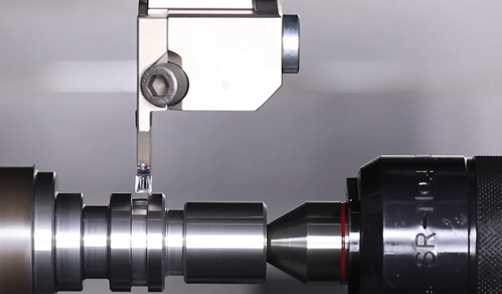
- Обеспечьте правильную посадку и зажим вставки в держателе инструмента.
- Очистите карман вставки и зажимные поверхности перед установкой
- Используйте динамометрический ключ, чтобы приложить правильное усилие зажима.
- Используйте рекомендуемые параметры резки, указанные производителем пластин.
- Начните с консервативных скоростей и подач, затем оптимизируйте по результатам.
- Рассмотрите возможность использования калькуляторов параметров резания или приложений, предоставляемых компаниями, производящими инструменты.
- Поддерживайте достаточный поток охлаждающей жидкости для управления тепловыделением и отводом стружки.
- Используйте охлаждающую жидкость под высоким давлением, когда это возможно, для улучшения контроля стружки
- Убедитесь, что сопла охлаждающей жидкости правильно выровнены относительно зоны резания
- Следите за износом вставок и заменяйте их до чрезмерного износа.
- Составьте график регулярных проверок в соответствии с вашими производственными требованиями
- Ищите признаки износа, такие как износ боковых поверхностей, кратеры или сколы на краях.
- Оптимизируйте стратегию обработки, чтобы свести к минимуму отклонение инструмента и вибрацию.
- Используйте минимально возможный выступ инструмента для обеспечения максимальной жесткости
- Рассмотрите возможность использования антивибрационных средств буровые штанги для глубокой рифления
- Рассмотрите возможность использования специализированных покрытий для улучшения характеристик вставки для конкретных материалов.
- Например, покрытия AlTiN для высокотемпературных применений или алмазные покрытия для цветных материалов.
- Регулярно очищайте и обслуживайте оснастку для обеспечения стабильной работы.
- Удаляйте скопления стружки со вставок и держателей инструмента
- Проверьте, нет ли повреждений на держателе инструмента или зажимном механизме.
- Экспериментируйте с различными конструкциями рассекателей для оптимизации управления стружкой.
- Правильное образование и отвод стружки имеют решающее значение для качества канавок и срока службы инструмента
- Используйте программное обеспечение CAM для моделирования и оптимизации траекторий движения инструмента для обработки канавок.
- Это поможет выявить потенциальные проблемы до начала обработки и повысить общую эффективность.
- Ведите подробный учет работы и износа вкладышей.
- Эти данные могут быть использованы при выборе инструмента и совершенствовании технологического процесса.
Внедрив эти передовые методы, вы сможете значительно повысить производительность, стабильность и экономическую эффективность операций фрезерования.
Заключение
Канавочные пластины - незаменимые инструменты в мире прецизионной обработки. Понимая различные типы, области применения и передовые методы работы с канавочными пластинами, механики могут добиться повышения производительности, улучшения качества деталей и снижения производственных затрат. Независимо от того, работаете ли вы с пластинами для обработки канавок с ЧПУ, пластинами для обработки канавок PCD или специализированными вариантами, такими как пластины для обработки торцов "ласточкин хвост", освоение этих универсальных режущих инструментов, несомненно, расширит ваши возможности в области обработки.
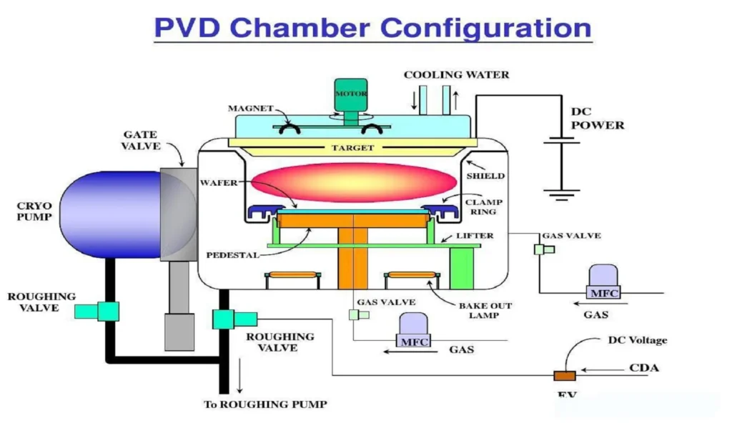
По мере развития технологий конструкции и материалы канавочных пластин будут совершенствоваться, чтобы соответствовать постоянно растущим требованиям современного производства. Постоянно разрабатываются инновационные геометрии, покрытия и марки пластин для повышения производительности, увеличения срока службы инструмента и расширения диапазона обрабатываемых материалов. К числу новых тенденций в технологии изготовления канавочных пластин относятся:
- Передовые технологии PVD и CVD покрытия для повышения износостойкости и удаления стружки
- Микрошлифовальные пластины для сверхточных применений в таких отраслях, как производство медицинского оборудования
- Интеграция датчиков для мониторинга износа инструмента в реальном времени и предиктивного обслуживания
- Разработка новых материалов подложки для повышения прочности и термостойкости
- Технологии аддитивного производства для изготовления нестандартных геометрий вставок
Если вы будете в курсе последних достижений в области технологии изготовления канавочных пластин и постоянно совершенствовать свои процессы обработки, вы сможете уверенно и точно решать даже самые сложные задачи. Помните, что для успешного выполнения операций по обработке канавок необходим комплексный подход, учитывающий не только саму пластину, но и всю систему обработки, включая станок, материал заготовки и условия резания. Обладая необходимыми знаниями, инструментами и методами, вы сможете раскрыть весь потенциал канавочных пластин и поднять свои возможности по обработке на новую высоту.