원스톱 CNC 카바이드 인서트 제조업체

Grooving Inserts: Essential Tools for Precision Machining

In the world of metalworking and CNC machining, grooving inserts play a crucial role in achieving precise and efficient results. These versatile cutting tools are indispensable for creating grooves, slots, and other intricate features in workpieces. Whether you’re a seasoned machinist or new to the field, understanding grooving inserts is essential for mastering various machining operations. This comprehensive guide will delve into the intricacies of grooving inserts, exploring their types, applications, and best practices to help you optimize your machining processes.

grooving inserts

What are Grooving Inserts?

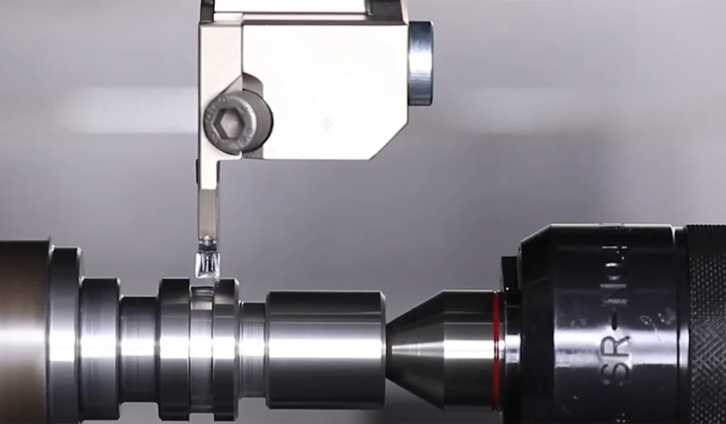
Grooving inserts are specialized cutting tools designed to create grooves, channels, or recesses in a workpiece. These inserts are typically made from hard, wear-resistant materials such as carbide, ceramic, or polycrystalline diamond (PCD). Grooving inserts are used in various machining operations, including turning, milling, and threading, to produce precise and consistent groove profiles.

The design of grooving inserts is carefully engineered to balance cutting efficiency, chip control, and tool life. Most grooving inserts feature a single cutting edge, which allows for precise control of the groove width and depth. The geometry of the cutting edge is optimized to reduce cutting forces and improve chip evacuation, ensuring a clean and accurate groove profile.

Types of Grooving Inserts

The world of grooving inserts is diverse, with various types designed to meet specific machining requirements. Let’s explore the main categories in detail:

1. CNC Grooving Inserts

CNC grooving inserts are specifically designed for use in computer numerical control (CNC) machines. These inserts offer high precision and repeatability, making them ideal for large-scale production environments. CNC grooving inserts come in various shapes and sizes to accommodate different groove profiles and machining parameters.

Key features of CNC grooving inserts include:

  • Precise dimensional tolerances for consistent results
  • Advanced chip breaker designs for improved chip control
  • Compatibility with high-speed machining operations
  • Optimized geometry for reduced cutting forces and improved tool life

Example application: A CNC grooving insert might be used in the automotive industry to create precise grooves for piston rings in engine blocks, ensuring optimal sealing and performance.

2. PCD Grooving Inserts

Polycrystalline diamond (PCD) grooving inserts are premium cutting tools known for their exceptional hardness and wear resistance. These inserts are particularly effective when machining abrasive materials such as aluminum alloys, composites, and non-ferrous metals. PCD grooving inserts offer extended tool life and superior surface finish quality.

Advantages of PCD grooving inserts include:

  • Extreme hardness and wear resistance
  • Excellent thermal conductivity for heat dissipation
  • Capability to maintain a sharp cutting edge for extended periods
  • Ideal for high-volume production of non-ferrous components

Example application: In the aerospace industry, PCD grooving inserts might be used to machine grooves in aluminum aircraft components, where precision and surface quality are critical.

3. Face Grooving Inserts

Face grooving inserts are designed for creating grooves on the face or end of a workpiece. These inserts are commonly used in turning operations to produce circular grooves, O-ring seats, and other radial features. Face grooving inserts often have a specialized geometry to ensure chip evacuation and minimize cutting forces.

Key characteristics of face grooving inserts:

  • Robust design to withstand radial cutting forces
  • Specialized chip breakers for efficient chip removal
  • Available in various widths to accommodate different groove sizes
  • Often feature a neutral or positive rake angle for smoother cutting action

Example application: In the hydraulic industry, face grooving inserts might be used to create precise O-ring grooves on the ends of cylindrical components, ensuring proper sealing in high-pressure systems.

4. Dovetail Face Grooving Inserts

더브테일 페이스 홈 가공 인서트 are a specialized type of face grooving tool used to create dovetail-shaped grooves. These grooves have a wider base than the opening, providing excellent mechanical locking for components such as O-rings or seals. Dovetail face grooving inserts require precise positioning and cutting parameters to achieve the desired profile.

Unique features of dovetail face grooving inserts:

  • Complex cutting edge geometry to produce the dovetail shape
  • Require specialized tool holders for proper orientation
  • Often used in conjunction with specialized programming techniques
  • Available in various angles to suit different dovetail specifications

Example application: In the production of industrial valves, dovetail face grooving inserts might be used to create secure seating for specialized seals, ensuring leak-free operation under high pressures.

5. Full Radius Grooving Inserts

Full radius grooving inserts feature a rounded cutting edge that produces a smooth, curved groove profile. These inserts are ideal for applications requiring stress relief or improved fluid flow. Full radius grooving inserts are commonly used in the automotive, aerospace, and hydraulic industries.

Benefits of full radius grooving inserts:

  • Produce smooth, stress-free groove profiles
  • Improve fluid dynamics in hydraulic and pneumatic systems
  • Reduce the risk of crack initiation in high-stress components
  • Often result in improved surface finish compared to sharp-cornered grooves

Example application: In the design of turbine components, full radius grooving inserts might be used to create smooth channels for cooling fluid flow, optimizing heat dissipation and engine efficiency.

6. Poly V Grooving Inserts

Poly V grooving inserts are specialized cutting tools designed for creating multiple V-shaped grooves simultaneously, typically used in the production of poly V-belts and pulleys. These inserts are crucial in automotive and industrial applications where power transmission through belts is required.

Key features of poly V grooving inserts include:

  • Multiple cutting edges arranged in a V-pattern
  • Precision-ground profiles to ensure accurate groove geometry
  • Available in various standard sizes to match different poly V-belt specifications
  • Often made from high-performance carbide grades for extended tool life

Advantages of using poly V grooving inserts:

  • Increased productivity by machining multiple grooves in a single pass
  • Consistent groove spacing and depth across the entire pulley surface
  • Improved surface finish compared to sequential single-groove operations
  • Reduced machining time and tool changes

Example application: In the automotive industry, poly V grooving inserts are used to manufacture serpentine belt pulleys for engine accessory drives, ensuring precise belt fit and optimal power transmission.

When selecting poly V grooving inserts, consider the following factors:

  • Number of grooves required
  • Groove pitch and profile specifications
  • Workpiece material (typically aluminum or steel for pulleys)
  • Machine rigidity and power capabilities

Proper use of poly V grooving inserts requires attention to:

  • Precise insert alignment in the tool holder
  • Adequate coolant supply to manage heat generation across multiple cutting edges
  • Careful control of cutting parameters to balance productivity and tool life

By incorporating poly V grooving inserts into your machining operations, you can significantly improve the efficiency and quality of pulley production, contributing to better-performing power transmission systems in various applications.

Grooving Insert Nomenclature

Understanding grooving insert nomenclature is crucial for selecting the right tool for your application. The naming convention typically includes information about the insert’s shape, size, clearance angle, and other characteristics. Let’s break down a typical grooving insert name:

MGMN 200-G

  • M: Insert shape (in this case, rhombic)
  • G: Clearance angle
  • M: Tolerance class
  • N: Cutting edge condition
  • 200: Insert size (e.g., 2mm thick)
  • G: Chip breaker designation

Additional nomenclature elements you might encounter include:

  • Coating type (e.g., TiN, AlTiN)
  • Grade (indicating the insert’s composition and intended application)
  • Special geometry indicators (e.g., wiper flat, horn design)

Familiarizing yourself with these codes will help you quickly identify and select the appropriate grooving insert for your specific machining needs. It’s also essential to consult manufacturer catalogs, as slight variations in nomenclature may exist between different tooling companies.

Applications of Grooving Inserts

Grooving inserts are used in a wide range of machining applications across various industries. Some common applications include:

  1. Creating O-ring grooves and seal seats
    • Example: Machining precise grooves in hydraulic cylinder end caps to ensure proper sealing
  2. Producing snap ring grooves
    • Example: Creating retaining ring grooves in automotive transmission components for secure assembly
  3. Machining undercuts and recesses
    • Example: Forming relief grooves in shaft collars to reduce stress concentrations
  4. Forming threads in turning operations
    • Example: Using specialized grooving inserts to produce custom thread profiles in high-precision fasteners
  5. Creating slots for retaining rings
    • Example: Machining grooves in motor shafts to accommodate circlips for bearing retention
  6. Producing grooves for fluid passage in hydraulic components
    • Example: Creating channels in valve bodies to control oil flow in hydraulic systems
  7. Machining grooves for keyways and splines
    • Example: Forming keyway slots in drive shafts for power transmission applications

The versatility of grooving inserts makes them essential tools in industries such as automotive, aerospace, oil and gas, and general manufacturing. By selecting the appropriate grooving insert and optimizing machining parameters, manufacturers can achieve high-precision results across a wide range of materials and component geometries.

Grooving vs. Threading: Understanding the Difference

While grooving and threading operations may seem similar, they serve different purposes and require distinct tooling:

Grooving:

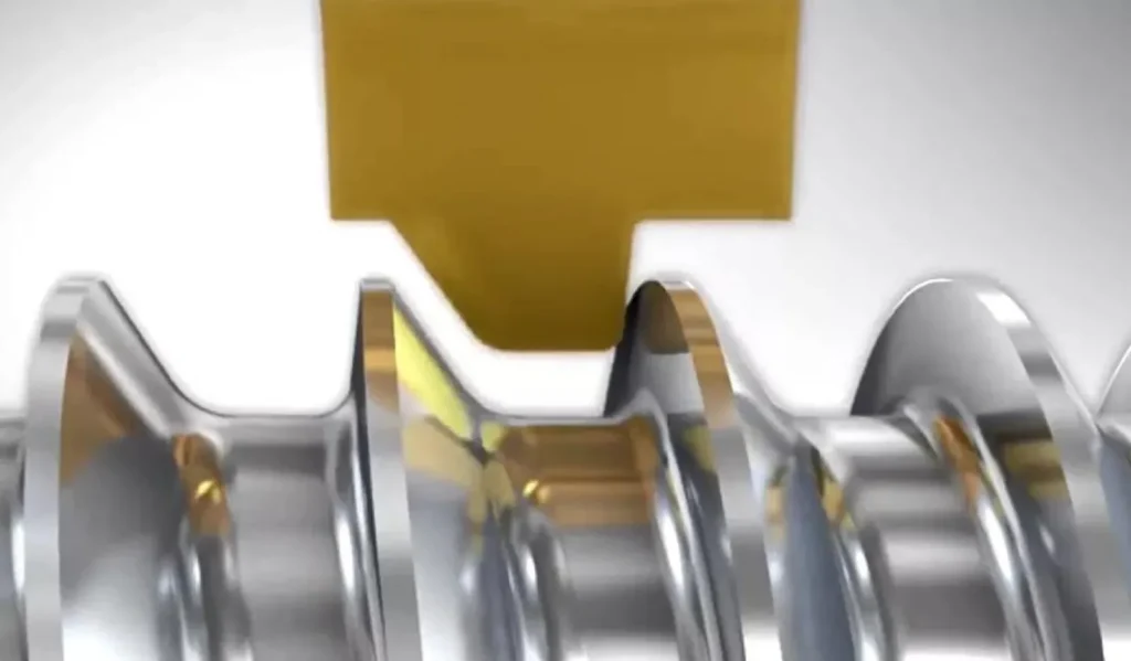
  • Creates a channel or recess in the workpiece, often with a rectangular or curved profile
  • Grooving inserts typically have a flat or slightly curved cutting edge
  • The tool moves radially into the workpiece, maintaining a constant depth
  • Primarily used for creating features like O-ring grooves, undercuts, and face grooves
  • Groove width is determined by the insert width

Threading:

  • Produces a helical ridge (external thread) or groove (internal thread) on a cylindrical surface
  • Threading inserts have a pointed or angled cutting edge designed to create the specific thread profile
  • The tool follows a helical path, gradually cutting deeper into the workpiece
  • Used for creating fastening features like bolts, nuts, and threaded connections
  • Thread profile is determined by the insert geometry and the helical tool path

The main difference lies in the tool movement and the resulting feature. Grooving involves plunging the tool radially into the workpiece, while threading requires a helical tool path to create the continuous spiral thread form.

Example comparison:

  • Grooving operation: Creating a 5mm wide, 2mm deep groove on a shaft for an O-ring
  • Threading operation: Producing an M10x1.5 external thread on the same shaft for attaching a nut

Grooving vs. Parting: Key Distinctions

Grooving and parting are related operations, but they serve different purposes and have distinct characteristics:

Grooving:

  • Creates a channel or recess in the workpiece without separating it into two pieces
  • The depth of the groove is typically less than the workpiece radius
  • Uses narrower inserts designed for precision and surface finish
  • Often requires multiple passes for deeper grooves
  • Primary goal is to create a specific feature or profile

Parting:

  • Involves cutting through the entire workpiece to separate it into two distinct parts
  • The cut depth equals or exceeds the workpiece radius
  • Uses wider, more robust inserts designed to withstand higher cutting forces
  • Generally performed in a single pass to completely sever the workpiece
  • Primary goal is to separate or remove a section of the workpiece

While both operations use similar tool geometries, parting tools are generally more robust to handle the complete separation of the workpiece. They often feature specialized chip breakers and coolant delivery systems to manage the challenges of deep cutting operations.

Example comparison:

  • Grooving operation: Creating a 3mm wide, 5mm deep circular groove on a 50mm diameter shaft
  • Parting operation: Cutting off a 10mm long section from the end of the same 50mm diameter shaft

Selecting the Right Grooving Insert

Choosing the appropriate grooving insert is crucial for achieving optimal results. Consider the following factors when selecting a grooving insert:

  1. Workpiece material: Match the insert grade to the material being machined.
    • For example, use a coated carbide insert for steel, or a PCD insert for aluminum alloys
  2. Groove dimensions: Select an insert width that corresponds to the desired groove width.
    • Consider using multiple passes with a narrower insert for wider grooves if necessary
  3. Cutting conditions: Consider factors such as cutting speed, feed rate, and depth of cut.
    • Higher speeds may require more wear-resistant grades or coatings
  4. Machine stability: Evaluate the rigidity of your setup and choose an insert that can handle the expected vibrations.
    • For less rigid setups, consider inserts with positive rake angles to reduce cutting forces
  5. Surface finish requirements: Select an insert with the appropriate chip breaker and edge preparation for the desired finish quality.
    • Wiper geometries can help achieve better surface finishes in certain applications
  6. Tool life expectations: Balance performance and cost by considering the insert’s wear resistance and replacement frequency.
    • Premium grades or coatings may have a higher upfront cost but can be more economical in high-volume production
  7. Coolant availability: Choose inserts with appropriate chip breakers and coatings based on your coolant delivery method (flood, high-pressure, or dry machining).
  8. Special geometries: Consider specialized insert designs for unique applications, such as Swiss-type machining or heavy-duty grooving.

By carefully evaluating these factors and consulting with tooling manufacturers or experienced machinists, you can select the optimal grooving insert for your specific application, ensuring efficient and high-quality results.

Best Practices for Using Grooving Inserts

To maximize the performance and longevity of your grooving inserts, follow these best practices:

  1. Ensure proper insert seating and clamping in the tool holder.
    • Clean the insert pocket and clamping surfaces before installation
    • Use a torque wrench to apply the correct clamping force
  2. Use the recommended cutting parameters provided by the insert manufacturer.
    • Start with conservative speeds and feeds, then optimize based on results
    • Consider using cutting parameter calculators or apps provided by tooling companies
  3. Maintain adequate coolant flow to manage heat generation and chip evacuation.
    • Use high-pressure coolant when possible for improved chip control
    • Ensure coolant nozzles are properly aligned with the cutting zone
  4. Monitor insert wear and replace inserts before they become excessively worn.
    • Establish a regular inspection schedule based on your production requirements
    • Look for signs of wear such as flank wear, crater wear, or edge chipping
  5. Optimize your machining strategy to minimize tool deflection and vibration.
    • Use the shortest possible tool overhang to maximize rigidity
    • Consider using anti-vibration boring bars for deep grooving operations
  6. Consider using specialized coatings to enhance insert performance for specific materials.
    • For example, AlTiN coatings for high-temperature applications or diamond coatings for non-ferrous materials
  7. Regularly clean and maintain your tooling to ensure consistent performance.
    • Remove built-up edge (BUE) and chip accumulation from inserts and tool holders
    • Check for any damage to the tool holder or clamping mechanism
  8. Experiment with different chip breaker designs to optimize chip control.
    • Proper chip formation and evacuation are critical for groove quality and tool life
  9. Use CAM software to simulate and optimize grooving tool paths.
    • This can help identify potential issues before actual machining and improve overall efficiency
  10. Keep detailed records of insert performance and wear patterns.
    • This data can inform future tooling selections and process improvements

By implementing these best practices, you can significantly improve the performance, consistency, and cost-effectiveness of your grooving operations.

결론

Grooving inserts are indispensable tools in the world of precision machining. By understanding the various types, applications, and best practices associated with grooving inserts, machinists can achieve higher productivity, improved part quality, and reduced manufacturing costs. Whether you’re working with CNC grooving inserts, PCD grooving inserts, or specialized variants like dovetail face grooving inserts, mastering the use of these versatile cutting tools will undoubtedly enhance your machining capabilities.

As technology continues to advance, grooving insert designs and materials will evolve to meet the ever-increasing demands of modern manufacturing. Innovations in insert geometries, coatings, and grades are constantly being developed to improve performance, extend tool life, and expand the range of machinable materials. Some emerging trends in grooving insert technology include:

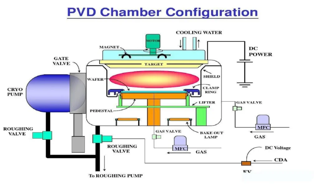
  • Advanced PVD and CVD coatings for improved wear resistance and chip evacuation
  • Micro-grooving inserts for ultra-precision applications in industries like medical device manufacturing
  • Integration of sensors for real-time tool wear monitoring and predictive maintenance
  • Development of new substrate materials for improved toughness and thermal stability
  • Additive manufacturing techniques for producing custom insert geometries

By staying informed about the latest developments in grooving insert technology and continuously refining your machining processes, you’ll be well-equipped to tackle even the most challenging machining tasks with confidence and precision. Remember that successful grooving operations require a holistic approach, considering not only the insert itself but also the entire machining system, including the machine tool, workpiece material, and cutting conditions. With the right knowledge, tools, and techniques, you can unlock the full potential of grooving inserts and take your machining capabilities to new heights.

이 공유:

코멘트를 남겨주세요

귀하의 이메일 주소는 공개되지 않습니다. 필요 입력 사항은 표시되어 있습니다 *

맨위로 스크롤
× 어떻게 도와드릴까요?