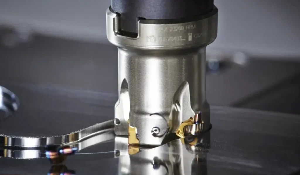
How to Choose Thread Whirling Inserts for Bone Screw Machining
Selecting a thread whirling insert for a bone screw is not simply a matter of matching the thread pitch.
The finished thread profile is determined by several connected factors, including the major and minor diameters, flank angles, crest and root radii, thread hand, helix angle, cutter diameter, insert position and whirling-head configuration.
This is especially important when machining bone screws from titanium alloys. Bone screw threads are often deeper and more asymmetrical than conventional machine-screw threads. They may also include customer-specific crest shapes, root transitions or self-tapping features.
A properly selected insert should therefore be based on the complete bone screw drawing—not only on a pitch value or a basic thread designation.
This guide explains the most important factors to consider when choosing thread whirling inserts for titanium bone screw machining.
Why Is Thread Whirling Used for Bone Screw Machining?
Thread whirling is widely used to produce long, slender screws with deep or special thread profiles.
During the process, the whirling cutter rotates at high speed around the workpiece. The workpiece rotates relatively slowly, while the machine feed is synchronized with the required thread pitch or lead. The whirling head is normally inclined according to the helix angle of the thread.
This configuration allows complex thread profiles to be produced in a single pass and can reduce the cutting load applied to a slender workpiece. Commercial tooling systems are specifically offered for bone screws, spinal screws, dental implants and other long medical components.
However, the advantages of thread whirling depend heavily on the insert profile and cutter-body setup. An incorrect insert can cause:
- Incorrect flank geometry
- Oversized or undersized thread diameters
- Excessive burr formation
- Poor crest or root definition
- Chatter marks or facets
- Premature insert chipping
- Inconsistent surface finish
- Short and unpredictable tool life
For this reason, insert selection should begin with the finished bone screw—not with the insert catalog.
1. Start with the Complete Bone Screw Drawing
The complete screw drawing is the most important document for selecting or designing a bone screw thread whirling insert.
At minimum, the drawing should identify:
- Major diameter
- Minor diameter
- Pitch
- Lead
- Number of thread starts
- Right-hand or left-hand thread
- Thread length
- Flank angles
- Crest dimensions
- Root dimensions
- Crest and root radii
- Dimensional tolerances
- Surface-finish requirements
- Burr-control requirements
Where applicable, the manufacturer should also identify the bone screw standard or the customer’s proprietary thread designation.
ASTM F543 covers requirements for metallic medical bone screws and identifies HA, HB, HC and HD screw types. HA and HB screws use asymmetrical thread forms, while HC and HD screws use symmetrical thread forms. ISO 5835 specifies dimensions and tolerances for metal bone screws with asymmetrical threads and distinguishes between shallow- and deep-thread designs.
A custom screw should not automatically be classified as an ISO or ASTM profile simply because it resembles a standard bone screw. The complete dimensions must be checked.
2. Why Thread Pitch Alone Is Not Enough
Two bone screws can have the same pitch while requiring completely different whirling inserts.
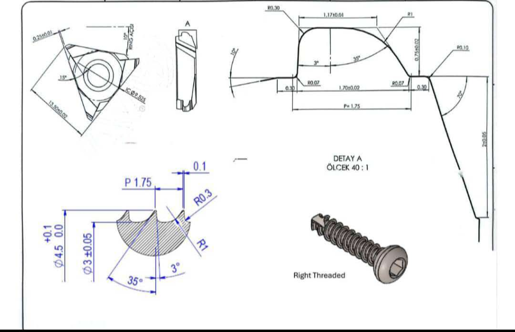
The two example drawings below demonstrate this clearly.
Example Profile A
The first drawing shows a right-hand thread with the following principal dimensions:
| Parameter | Example A |
|---|---|
| Thread pitch | 1.75 mm |
| Major diameter | Approximately Ø4.5 mm |
| Minor diameter | Approximately Ø3.0 mm |
| Principal flank angle | 35° |
| Opposite flank angle | 3° |
| Selected profile radii | R0.3 and R1 |
| Thread type | Asymmetrical, right-hand |
Example Profile B
The second drawing also specifies a right-hand thread with a pitch of 1.75 mm, but its remaining geometry is substantially different:
| Parameter | Example B |
|---|---|
| Thread pitch | 1.75 mm |
| Major diameter | Approximately Ø4.0 mm |
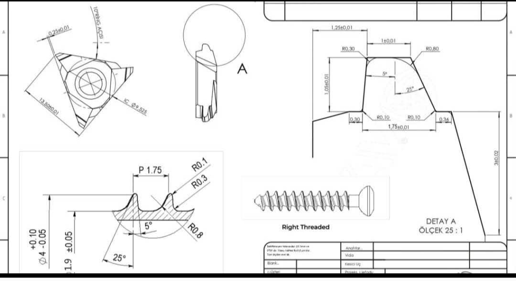
| Minor diameter | Approximately Ø1.9 mm |
| Principal flank angle | 25° |
| Opposite flank angle | 5° |
| Selected profile radii | R0.1, R0.3 and R0.8 |
| Thread type | Asymmetrical, right-hand |
Although both screws use a nominal pitch of 1.75 mm, their thread depths, flank angles, crest shapes and transition radii are different.
The approximate radial thread depth can be compared using:
Radial thread depth = (major diameter − minor diameter) ÷ 2
For Example A:
(4.5 − 3.0) ÷ 2 = approximately 0.75 mm
For Example B:
(4.0 − 1.9) ÷ 2 = approximately 1.05 mm
Example B therefore requires a considerably deeper cutting profile, even though the pitch is the same.
The two inserts are not interchangeable.
Comparison of the Two P1.75 Profiles
| Selection factor | Example A | Example B | Effect on insert design |
|---|---|---|---|
| Pitch | 1.75 mm | 1.75 mm | Similar axial tooth spacing |
| Major diameter | Ø4.5 mm | Ø4.0 mm | Changes the finished outside envelope |
| Minor diameter | Ø3.0 mm | Ø1.9 mm | Produces a different cutting depth |
| Radial thread depth | Approx. 0.75 mm | Approx. 1.05 mm | Changes cutting load and profile height |
| Main flank angle | 35° | 25° | Requires a different insert flank |
| Opposite angle | 3° | 5° | Changes asymmetry and profile compensation |
| Radii | R0.3/R1 | R0.1/R0.3/R0.8 | Requires different ground transitions |
| Interchangeable insert | No | No | Separate profile designs are required |
This comparison illustrates one of the most important rules in bone screw tooling:
Never select a full-profile bone screw whirling insert by pitch alone.
3. Distinguish Between the Finished Screw Profile and the Insert Profile
A common assumption is that the cutting edge of the insert should be an exact two-dimensional copy of the finished bone screw profile.
This is not always correct.
In thread whirling, the insert travels around the workpiece while the cutter is inclined relative to the workpiece axis. The actual cutting envelope is affected by:
- Thread helix angle
- Whirling-ring diameter
- Insert cutting position
- Cutter eccentricity
- Workpiece diameter
- Cutter inclination
- Machine kinematics
- Number and position of inserts
Consequently, the insert profile may require geometric compensation to produce the specified profile on the screw.
Specialist tooling manufacturers describe this as compensation for the profile distortion generated by the whirling process. The issue becomes particularly important for multi-start threads, large helix angles, sharp crests and demanding profile tolerances.
The finished screw drawing should therefore be used as the design target, while the final insert profile should be calculated according to the complete whirling configuration.
4. Confirm the Titanium Alloy Grade
For the examples in this article, the workpiece material is identified only as a titanium alloy.
This is sufficient for an initial discussion, but not for final cutting-tool approval.
“Titanium alloy” can refer to materials with different:
- Chemical compositions
- Strength levels
- Hardness values
- Heat-treatment conditions
- Machining behavior
- Adhesion tendencies
- Thermal characteristics
Before final insert selection, the customer should provide the exact material designation, specification and bar-stock condition.
The insert supplier should ask for information such as:
- Exact titanium grade
- Applicable ASTM, ISO or customer material standard
- Material hardness
- Bar-stock diameter
- Annealed or heat-treated condition
- Cold-worked or hot-worked condition
- Surface condition of the bar
Without this information, cutting data and tool-life expectations should be treated as preliminary.
5. Select a Geometry Suitable for Titanium Alloy
Titanium bone screw machining generally benefits from an insert geometry that limits cutting forces and controls adhesion at the cutting edge.
Important design considerations include:
Cutting-edge sharpness
A sharp cutting edge can reduce cutting forces and improve the definition of the thread crest and flanks.
However, the edge should not be made so fragile that it becomes vulnerable to microchipping. The correct edge preparation depends on the cutting load, carbide substrate, cutter runout and stability of the complete process.
Rake geometry
The rake surface should support chip flow away from the cutting zone. A suitable positive or application-specific rake geometry can help reduce cutting resistance.
Clearance geometry
Adequate clearance is necessary to prevent rubbing between the insert flank and the workpiece. Clearance must be assessed together with the helix angle and cutter inclination.
Crest and root transitions
Small radii such as R0.1 or R0.3 require accurate insert grinding and consistent edge preparation. Larger blended radii, such as R0.8 or R1, affect both the cutting envelope and the amount of material removed.
Chip space
A deeper thread profile removes more material. The insert and cutter body must provide enough chip space to prevent recutting or chip packing.
Commercial thread-whirling systems also emphasize sharp cutting edges and PVD-coated inserts for complex bone screw profiles.
6. Evaluate the TiAlSiN Coating as Part of the Complete Insert System
The inserts in these examples use a TiAlSiN coating.
TiAlSiN is a PVD hard coating used on cutting tools for demanding machining applications. Research has examined its fine coating structure, hardness, wear resistance and performance when cutting difficult-to-machine materials, including titanium alloys.
However, the coating name alone does not define the performance of the insert.
The final result also depends on:
- Carbide substrate
- Grain size
- Cobalt content
- Coating composition
- Coating thickness
- Deposition method
- Coating adhesion
- Edge preparation before coating
- Post-coating edge treatment
- Cutting speed
- Coolant delivery
- Cutter runout
For a precision bone screw insert, coating thickness must also be controlled because excessive or uneven coating around a small radius can affect the final cutting-edge geometry.
TiAlSiN should therefore be described as one part of the tooling system—not as a universal solution for every titanium alloy.
A suitable technical statement for this application is:
The TiAlSiN coating is selected to support wear resistance and edge stability during titanium-alloy machining. Final performance must be validated together with the carbide substrate, cutting geometry, coolant strategy and actual titanium grade.
7. Check the Insert and Cutter-Body Compatibility
A correctly ground thread profile is not enough. The insert must also match the whirling cutter body.
The supplied cutter-body drawings show a six-insert circular arrangement. They include insert pockets, clamping screws, locating features, cutter diameters, axial dimensions and runout requirements. One drawing shows a body diameter of approximately Ø45 mm, together with six replaceable inserts arranged around the internal cutting circle.
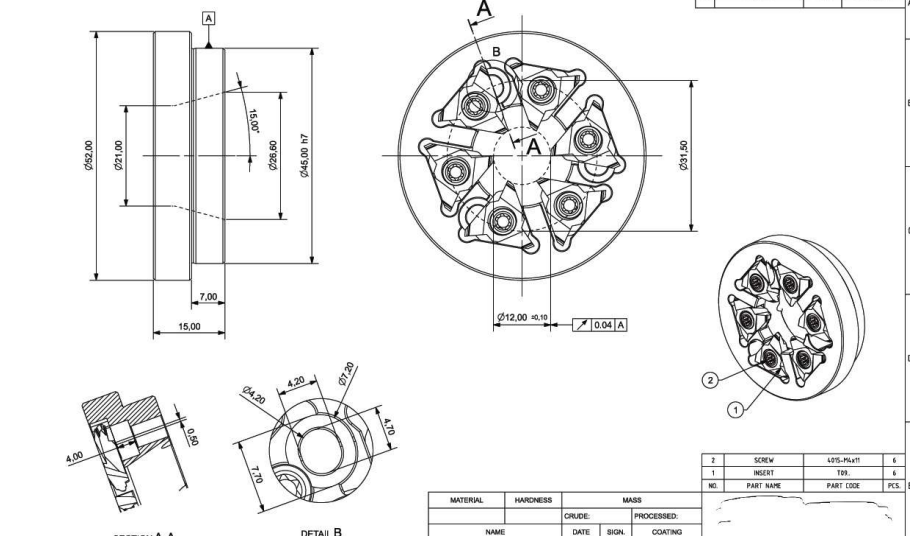
Before manufacturing or supplying replacement inserts, the following items should be confirmed:
- Cutter-body drawing
- Number of insert pockets
- Insert seat dimensions
- Insert thickness
- Inscribed-circle or overall insert dimensions
- Central-hole dimensions
- Clamping-screw specification
- Locating surfaces
- Insert orientation
- Pocket angle
- Cutting-circle diameter
- Cutter-body width
- Maximum permitted runout
- Machine-side mounting dimensions
Even when two inserts have a similar triangular appearance, differences in the locating surface, hole position, thickness or cutting-edge height can make them incompatible.
Why runout matters
In a six-insert cutter, every cutting edge should participate consistently in the cut.
If one insert is positioned farther inward than the others, it may perform little or no cutting. If one insert protrudes farther outward, it may carry an excessive share of the load.
Possible results include:
- Uneven insert wear
- Chipping of one cutting edge
- Periodic surface marks
- Inconsistent thread diameter
- Reduced tool life
- Increased vibration
Insert-seat cleanliness, screw condition and controlled tightening are therefore part of insert performance.
8. Confirm Thread Hand and Helix Angle
Both example screws are marked as right-hand threads.
Thread hand affects:
- Cutter rotation
- Workpiece rotation
- Feed direction
- Insert orientation
- Cutting-edge position
- Whirling-head setup
The thread helix angle must also be considered when setting the cutter.
In thread whirling, the cutter head is inclined to a specified helix angle while the cutter rotates at high speed and the bar stock rotates at a lower speed.
The helix angle is not determined by pitch alone. It is influenced by the lead and the effective thread diameter. When the thread diameter changes, the required whirling-ring setting may also change.
For a single-start thread:
Lead = pitch
For a multi-start thread:
Lead = pitch × number of starts
This is why the customer should provide both pitch and number of starts, rather than describing the thread only as “P1.75.”
9. Consider the Number of Inserts
The example cutter uses six inserts.
The appropriate number of inserts depends on:
- Cutter diameter
- Available pocket space
- Required production rate
- Feed per tooth
- Machine power
- Workpiece stability
- Thread depth
- Chip volume
- Surface-finish target
- Insert cost
- Cutter-body rigidity
More inserts do not automatically guarantee a better result.
Increasing the number of cutting edges may improve potential productivity, but it also reduces the available chip space and places greater importance on pocket accuracy and insert runout.
For a relatively deep titanium thread, chip evacuation and balanced tooth loading may be more important than simply maximizing the number of inserts.
10. Evaluate Coolant Delivery and Chip Evacuation
Titanium-alloy thread whirling requires careful control of heat and chips.
The coolant should reach the active cutting edges rather than only flooding the outside of the cutter body. The process should also prevent chips from becoming trapped between adjacent inserts.
Internal coolant systems have been developed for thread whirling to direct coolant toward the cutting edges. Tooling manufacturers associate this approach with reduced chip jamming, improved surface quality and longer tool life.
The following questions should be answered during tool selection:
- Is coolant delivered externally or internally?
- Does coolant reach every insert?
- Is the coolant filtered?
- Is the coolant pressure stable?
- Is there enough space for chips to leave the cutter?
- Are chips being recut?
- Is material building up on the rake face?
- Does the cutter body have coolant channels?
- Is the coolant compatible with the validated medical manufacturing process?
Coolant type and cutting parameters should be confirmed through production testing rather than copied from an unrelated machine.
11. Define the Required Screw Quality
The customer and insert supplier should agree on the inspection criteria before the cutting trial.
Thread-profile inspection
The inspection plan may include:
- Major diameter
- Minor diameter
- Pitch or lead
- Thread depth
- Flank angles
- Crest width
- Crest radius
- Root radius
- Thread-profile deviation
- Lead accuracy
- Thread length
Surface inspection
The manufacturer may also evaluate:
- Surface roughness
- Burr height
- Tearing
- Smearing
- Chatter marks
- Facets
- Built-up-edge marks
- Scratches caused by trapped chips
Production-performance inspection
Tooling performance should be evaluated using:
- Parts per cutting edge
- Wear consistency
- Frequency of chipping
- Cycle time
- Insert-change time
- First-piece adjustment time
- Scrap rate
- Batch-to-batch repeatability
- Tooling cost per accepted part
ASTM F543 also includes dimensional requirements and several mechanical test methods for metallic medical bone screws. Cutting-tool validation is only one part of the complete medical-device manufacturing and verification process.
The insert manufacturer should not claim that using a particular insert or coating automatically makes the finished screw compliant with a medical standard.
12. Standard or Custom Thread Whirling Insert?
A standard insert may be suitable when:
- The bone screw uses a fully defined standard profile
- The dimensions fall within the standard tooling range
- The cutter body is compatible
- The required tolerances can be achieved without special compensation
- Production testing confirms acceptable results
A custom insert is normally required when:
- The screw uses a proprietary profile
- Flank angles differ from standard profiles
- Special crest or root radii are specified
- The thread is unusually deep
- The screw has multiple starts
- The thread must be machined close to the head
- The cutter body has a customer-specific insert pocket
- Profile-distortion compensation is necessary
- An existing special insert must be replaced
The two P1.75 profiles examined in this article should be treated as separate custom designs because their diameters, depths, angles and radii are different.
A Practical Selection Process
A reliable selection process can be divided into seven steps.
Step 1: Review the complete bone screw drawing
Confirm every thread-profile dimension and tolerance.
Step 2: Identify the standard or proprietary profile
Do not assume that the screw follows ISO 5835 or ASTM F543 without verification.
Step 3: Confirm the exact titanium grade
Record the material specification, hardness and bar-stock condition.
Step 4: Review the machine and cutter-body configuration
Confirm the machine, whirling unit, cutter body, insert pocket and coolant system.
Step 5: Calculate the required insert profile
Account for the thread hand, helix angle, cutter diameter and whirling kinematics.
Step 6: Select the carbide, geometry and coating
Evaluate the substrate, cutting-edge preparation and TiAlSiN coating as one system.
Step 7: Conduct a controlled cutting trial
Inspect the screw profile, burr condition, surface finish, insert wear and process repeatability.
Information Required for a Custom Insert Quotation
To quote or design a custom bone screw thread whirling insert, the customer should provide:
- Complete bone screw drawing
- Enlarged thread-profile drawing
- Major diameter
- Minor diameter
- Pitch
- Lead
- Number of starts
- Right-hand or left-hand thread
- Helix angle, when available
- All flank angles
- Crest and root radii
- Exact titanium alloy grade
- Material hardness and condition
- Bar-stock diameter
- Machine brand and model
- Whirling-unit brand and model
- Cutter-body drawing
- Insert-pocket dimensions
- Current insert drawing or physical sample
- Number of inserts in the cutter body
- Coolant type and delivery method
- Current cutting parameters
- Required surface finish
- Burr requirement
- Current tooling problem
- Expected production quantity
- Target tool life
- Inspection report or profile measurement, when available
Common Mistakes When Selecting Bone Screw Whirling Inserts
Selecting the insert only by pitch
The two P1.75 examples show why this approach is unreliable.
Failing to provide the minor diameter
The minor diameter determines the thread depth and has a major effect on cutting load.
Ignoring small radii
R0.1, R0.3, R0.8 and R1 transitions cannot be treated as equivalent.
Copying the finished profile directly onto the insert
Whirling-process compensation may be required.
Describing the material only as titanium
The exact titanium grade should be confirmed before finalizing cutting data.
Selecting the coating independently
TiAlSiN coating, carbide grade, edge preparation and geometry should be evaluated together.
Ignoring cutter-body compatibility
Similar-looking triangular inserts may have different locating and mounting dimensions.
Ignoring insert runout
Unequal tooth loading can produce premature wear and poor thread quality.
Comparing only the insert price
Tooling should be compared based on the cost per accepted screw, not only the purchase price per insert.
Frequently Asked Questions
Can the same insert machine both P1.75 bone screws shown in the examples?
No. Although the pitch is the same, the major diameter, minor diameter, thread depth, flank angles and radii are different. Separate full-profile inserts are required.
Is TiAlSiN suitable for titanium bone screw machining?
TiAlSiN is used as a wear-resistant cutting-tool coating for demanding materials, including titanium alloys. However, suitability must be validated with the exact titanium grade, carbide substrate, geometry, coolant system and cutting parameters.
Is the titanium grade necessary for making the insert profile?
The finished geometric profile can be designed from the screw and cutter drawings. However, the titanium grade is important for selecting the carbide substrate, edge preparation, coating strategy and cutting parameters.
Can the finished bone screw profile be copied directly onto the insert?
Not always. The whirling angle, cutter diameter and cutting motion can distort the generated profile, so compensation may be necessary.
Why does cutter-body information matter?
The insert must fit the pocket, locating surfaces and clamping system. The cutter diameter and insert position also affect the generated thread geometry.
Is a six-insert cutter always the best choice?
No. Six inserts may provide a suitable balance for a particular cutter body, but the optimum tooth count depends on the thread depth, chip volume, machine power, surface requirement and production target.
What should be measured during the first cutting trial?
At minimum, measure the major and minor diameters, profile angles, crest and root geometry, pitch or lead, surface finish and burr condition. Insert wear and tooth-to-tooth load distribution should also be checked.
Conclusion
Choosing a bone screw thread whirling insert requires more information than the thread pitch.
The two reference screws in this guide both have a pitch of 1.75 mm, but they require different inserts because their thread depths, flank angles, diameters and radii are not the same.
A reliable insert selection should consider:
- The complete finished screw profile
- The exact titanium alloy grade
- Thread hand and helix angle
- Cutter-body and insert-pocket compatibility
- Profile compensation
- Carbide substrate
- Cutting-edge geometry
- TiAlSiN coating
- Coolant delivery
- Inspection and production requirements
For customer-specific bone screws, the most reliable approach is to design the insert from the complete screw and cutter-body drawings and then validate it through a controlled cutting trial.
Need a custom thread whirling insert for a titanium bone screw?
Send us the bone screw drawing, cutter-body drawing, titanium grade and current machining information. Our engineering team will evaluate the profile and recommend a suitable custom insert solution.