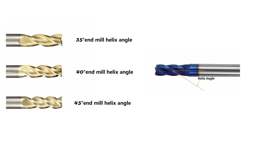
Führung Schaftfräser Helix Winkel
Der Schrägungswinkel des Schaftfräsers ist einer der wichtigsten geometrischen Parameter, der die Schnittleistung, die Werkzeugstandzeit und die Bearbeitungsqualität erheblich beeinflusst. Dieses spiralförmige Merkmal bestimmt nicht nur, wie effektiv das Werkzeug durch verschiedene Materialien schneidet, sondern beeinflusst auch die Spanabfuhr, die Wärmeableitung und die allgemeine Schnittstabilität. Ganz gleich, ob Sie mit Aluminium, rostfreiem Stahl oder gehärteten Werkstoffen arbeiten, die richtige Wahl des Spiralwinkels kann Ihre Bearbeitungsergebnisse und die Langlebigkeit des Werkzeugs erheblich verbessern.
Wenn Sie den Artikel nicht lesen möchten, können Sie sich auch die Vergleichstabelle der verschiedenen Schrägungswinkel von Schaftfräsern am Ende ansehen.
Was macht einen Schaftfräser-Spiralwinkel aus?
Der Schrägungswinkel Schaftfräser ist geometrisch definiert als der Winkel zwischen dem Tangentenvektor der Schneide und der Rotationsachse des Werkzeugs. Einfacher ausgedrückt, ist es der Winkel der spiralförmigen Nuten, die um den Werkzeugkörper gewickelt sind. Dieser Winkel wirkt sich direkt darauf aus, wie die Schneide in das Werkstückmaterial eingreift und bestimmt die bei der Bearbeitung auftretenden Schnittkräfte.
Helix-Winkelformel und mathematischer Ausdruck
Für zylindrische Schaftfräser kann die Schrägungswinkelformel durch diese grundlegende Gleichung ausgedrückt werden:
tan(α) = r/T
Wo:
- α ist der Schrägungswinkel
- r ist der Radius des Schaftfräsers
- T ist die Steigung (der axiale Abstand, der für eine vollständige Umdrehung der Spirale erforderlich ist)
In einem umfassenderen mathematischen Kontext spiegelt der Schrägungswinkel das Verhältnis zwischen der tangentialen Geschwindigkeitskomponente und den kombinierten radialen und axialen Geschwindigkeitskomponenten wider:
tan(β) = V₍ₜ₎/√(V₍ᵣ₎² + V₍ᶻ₎²)
Das Verständnis dieser Zusammenhänge ist für die Verwendung eines Schrägungswinkel-Rechners zur Bestimmung der optimalen Konstruktionsparameter für bestimmte Anwendungen unerlässlich.
Dynamische Variation in komplexen Werkzeugen
Bei komplexeren rotierenden Schneidwerkzeugen wie Kugelfräsern und kegelförmigen Werkzeugen kann der Schrägungswinkel an verschiedenen Positionen der Schneidkante variieren. Zum Beispiel:
- Bei Kugelkopffräsern ändert sich der Schrägungswinkel allmählich vom zylindrischen Teil zur kugelförmigen Spitze.
- Bei Bohrern ist der Schrägungswinkel in der Regel an der Außenkante am größten (etwa 25°-32°) und nimmt zur Mitte hin ab (bis zu 6°).
- Bei kegelförmigen Schaftfräsern muss der Schrägungswinkel sorgfältig ausgelegt werden, um eine gleichmäßige Schneidmechanik über das gesamte Werkzeug zu erhalten.
Gängige Schaftfräser-Spiralwinkel-Varianten
Standard-Hartmetallfräser weisen in der Regel Schrägungswinkel in drei Hauptkategorien auf:
- Standardspirale (30°): Bietet ein gutes Gleichgewicht zwischen Steifigkeit und Schnittleistung
- Mittlere Schräglage (45°): Wird oft als "Power-Helix-Winkel" bezeichnet und bietet einen verbesserten Späneabtransport
- Schaftfräser mit hoher Steigung (60°): Spezialisiert für anspruchsvolle Materialien und Hochleistungsanwendungen
Der empfohlene Auslegungsbereich liegt im Allgemeinen zwischen 30° und 45°. Winkel über 45° können die Steifigkeit des Werkzeugs beeinträchtigen, während Winkel unter 30° zu Vibrationen und Rattern während der Bearbeitung führen können.
Wie sich der Helix-Winkel auf die Bearbeitungsleistung auswirkt
Schnittkräfte und Werkzeuggeometrie
Ein größerer Schrägungswinkel des Fräsers ist effektiv:
- Reduziert radiale Schnittkräfte
- Verbessert den tatsächlichen Arbeitswinkel
- Erzeugt schärfere Schnittkanten
- Verteilt die Schnittlast auf einen größeren Teil der Kante
Dies ist besonders vorteilhaft bei der Auswahl eines Schrägungswinkels für Aluminium und andere weiche Werkstoffe, bei denen die Minimierung der Aufbauschneide und die Gewährleistung eines reibungslosen Spanflusses entscheidend sind.
Stabilitäts- und Schwingungskontrolle
Der Schrägungswinkel ermöglicht einen allmählichen Eingriff des Werkzeugs in das Werkstück und erhöht die Anzahl der Schneiden, die gleichzeitig in Kontakt sind. Diese Eigenschaft:
- Minimiert die Stoßbelastung
- Reduziert Vibrationen
- Sorgt für ein sanfteres Schneiden
- Verbessert die Qualität der Oberfläche
Ein Beispiel für diesen Vorteil sind zylindrische Schaftfräser, die für unterbrochene Schneidoperationen verwendet werden, wo höhere Schrägungswinkel die Schnittkräfte gleichmäßiger verteilen und so den Werkzeugverschleiß verringern.
Wärmemanagement und Langlebigkeit der Werkzeuge
Der Schrägungswinkel hat einen erheblichen Einfluss auf die Wärmeerzeugung und -abfuhr während der Bearbeitung:
- Höhere Schrägungswinkel verlängern den Kontaktweg zwischen Span und Werkzeug und fördern so eine bessere Wärmediffusion
- Dieser erweiterte Kontakt verringert die Wärmekonzentration an einem einzigen Punkt
- Verbesserte Wärmeverteilung hilft, die Integrität der Schneidkante zu erhalten
- Effizientere Kühlung ermöglicht höhere Schnittgeschwindigkeiten bei geeigneten Anwendungen
Materialspezifische Auswahl des Spiralwinkels
Schaftfräser Helix Winkel für Aluminium
Bei der Bearbeitung von Aluminium ist die Wahl des richtigen Schrägungswinkels entscheidend:
- Empfohlener Bereich: 40°-60°
- Schaftfräser mit hoher Steigung (etwa 45°-60°) werden bevorzugt
- Zu den Vorteilen gehören eine geringere Wärmeentwicklung, eine verbesserte Spanabfuhr und die Vermeidung von Materialanhaftungen.
- Der hohe Schrägungswinkel erhöht die Schärfe der Schneidkanten, was für dieses weiche Material ideal ist
- Bei Aluminiumlegierungen für die Luft- und Raumfahrt (wie 7075-T6) bieten Schrägungswinkel von 50°-55° optimale Leistung.
- Bei der Hochgeschwindigkeitsbearbeitung von Aluminium können Spiralwinkel von 50°+ in Verbindung mit einer geeigneten Beschichtungstechnologie außergewöhnliche Ergebnisse erzielen
Schaftfräser Helix Winkel für rostfreien Stahl
Der Schrägungswinkel von Schaftfräsern für rostfreien Stahl stellt besondere Herausforderungen dar, die spezielle Überlegungen erfordern:
- Empfohlener Bereich: 35°-45°
- Mittlere bis hohe Schrägungswinkel funktionieren am besten
- Die 45°-Powerhelix" bietet ein hervorragendes Gleichgewicht zwischen Schneidleistung und Wärmemanagement
- Bei härteren Edelstahlsorten sorgt ein 60°-Spiralwinkel für einen besseren Spanbruch und verhindert Kaltverfestigung
- Austenitische nichtrostende Stähle (304, 316) profitieren von Schrägungswinkeln im Bereich von 40°-45°.
- Martensitische und ausscheidungsgehärtete nichtrostende Stähle können für eine bessere Kantenfestigkeit niedrigere Winkel (35°-40°) erfordern.
Helix-Winkel für harte Materialien
Für gehärtete Stähle (HRC ≥ 50) und andere schwer zerspanbare Werkstoffe:
- Empfohlener Bereich: 30° oder weniger für maximale Steifigkeit
- Schaftfräser mit variabler Spiralform können optimal sein
- Niedrigere Winkel sorgen für eine bessere Unterstützung der Kante und mehr Widerstand gegen Abplatzungen
- Die erhöhte Werkzeugfestigkeit kompensiert die höheren erforderlichen Schnittkräfte
- Für Werkzeugstähle und gehärtete Formteile bieten Winkel von 25°-30° das beste Gleichgewicht zwischen Leistung und Werkzeugstandzeit.
- Bei der Bearbeitung von Titanlegierungen hilft ein moderater Schrägungswinkel (35°-40°), die schlechte Wärmeleitfähigkeit des Materials zu bewältigen.
Erweiterte Helix-Designs
Variable Helix-Schaftfräser-Technologie
Schaftfräser mit variabler Spiralisierung weisen unterschiedliche Spiralisierungswinkel entlang desselben Schneidwerkzeugs auf, die in der Regel zwischen 30° und 45° liegen und stufenweise variieren. Diese speziellen Werkzeuge bieten mehrere Vorteile:
- Störung der harmonischen Resonanzmuster
- Deutliche Verringerung von Rütteln und Vibrationen
- Verbesserte Stabilität bei Hochgeschwindigkeitsbearbeitung
- Verbesserte Qualität der Oberflächenbehandlung
Diese fortschrittliche Konstruktion ist besonders vorteilhaft bei der Bearbeitung komplexer Konturen oder bei der Arbeit mit weniger starren Aufbauten.
Integration des Designs mit variabler Steigung
Moderne Schneidwerkzeuge kombinieren häufig variable Spiralwinkel mit variablen Steigungsabständen:
- Die variable Teilung stört das Timing der Zahnstöße
- In Kombination mit variablen Schrägungswinkeln entsteht so ein leistungsstarkes Anti-Vibrationssystem
- Diese Werkzeuge eignen sich hervorragend für anspruchsvolle Anwendungen, wie z. B. das Tieflochbohren und die Dünnwandbearbeitung.
- Tests in der Industrie haben gezeigt, dass bei bestimmten Anwendungen bis zu 80% weniger Oberwellen auftreten
Richtungsbezogene Überlegungen
Auch die Richtung des Schrägungswinkels spielt eine Rolle:
- Rechtsgängige Spiralwinkel erleichtern den Abtransport der Späne nach oben
- Linke Spiralwinkel leiten Späne nach unten
- Die Auswahl sollte zur Spindeldrehrichtung der Werkzeugmaschine passen
- Bei einigen Materialien kann die Richtung die Qualität der bearbeiteten Kante beeinflussen.
- Bei horizontalen Bearbeitungszentren hat die Wendelrichtung einen erheblichen Einfluss auf die Spankontrolle und -abfuhr.
Verwendung eines Helix-Winkel-Rechners für die optimale Auswahl
Wenn Präzision entscheidend ist, kann ein Schrägungswinkelrechner helfen, den idealen Winkel für bestimmte Anwendungen zu bestimmen. Zu den zu berücksichtigenden Faktoren gehören:
- Materialeigenschaften (Härte, Wärmeleitfähigkeit)
- Steifigkeit und Leistung der Maschine
- Gewünschte Oberflächenbeschaffenheit
- Anforderungen an die Chipkontrolle
- Erwartungen an die Lebensdauer der Werkzeuge
Online-Rechner verwenden häufig die bereits erwähnte Schrägungswinkelformel und ermöglichen es den Bearbeitern, ihre spezifischen Parameter einzugeben, um individuelle Empfehlungen zu erhalten.
Praktisches Berechnungsbeispiel
Um zu wissen, wie ein Schrägungswinkel-Rechner funktioniert:
Für einen Schaftfräser mit 12 mm Durchmesser und einer Steigung (T) von 40 mm:
- r = 6 mm (Radius)
- T = 40mm (Blei)
- tan(α) = 6/40 = 0,15
- α = tan-¹(0,15) ≈ 8,53°
Dieser Winkel wäre jedoch für die meisten Anwendungen zu klein. Durch Einstellen der Steigung auf 10 mm:
- tan(α) = 6/10 = 0,6
- α = tan-¹(0,6) ≈ 31°
Dies zeigt, wie Werkzeugkonstrukteure den Steigungswert manipulieren, um die gewünschten Spiralwinkel für bestimmte Anwendungen zu erreichen.
Balance zwischen Werkzeugstandzeit und Bearbeitungspräzision
Um den optimalen Schrägungswinkel eines Schaftfräsers zu finden, müssen mehrere konkurrierende Faktoren gegeneinander abgewogen werden:
- Standzeit: Spiralwinkel bis zu 40° verbessern im Allgemeinen die Standzeit der Werkzeuge durch die Verteilung der Schnittkräfte, aber Winkel, die diesen Wert überschreiten, können die Steifigkeit verringern.
- Präzision bei der Bearbeitung: Moderate Schrägungswinkel (30°-40°) bieten das beste Gleichgewicht zwischen vertikaler Toleranz und Ebenheit
- Materialverformung: Bei der Bearbeitung von dünnwandigen Bauteilen verringern kleinere Spiralwinkel die Axialkräfte, die zu Verformungen führen könnten.
- Stromverbrauch: Höhere Schrägungswinkel erfordern in der Regel weniger Energie, was möglicherweise höhere Schnittparameter ermöglicht.
Industrieanwendungen und Fallstudien
Herstellung von Komponenten für die Luft- und Raumfahrt
Bearbeitung in der Luft- und Raumfahrt:
- Hoch Spiralförmige Schaftfräser (45°-60°) werden bevorzugt für Aluminiumbauteile eingesetzt
- Schaftfräser mit variabler Spiralform sind für Titanrahmenkomponenten unerlässlich, um Vibrationen zu vermeiden.
- Bei Inconel und anderen Superlegierungen auf Nickelbasis führen spezielle Spiralwinkel von 35°-40° in Kombination mit geeigneten Beschichtungen zu optimalen Ergebnissen.
Werkzeug- und Formenbau
Für Anwendungen im Formenbau:
- Mittlere Spiralwinkel (35°-40°) bieten die beste Balance für Semi-Finishing-Bearbeitungen
- Niedrigere Spiralwinkel (25°-30°) eignen sich hervorragend für Schlichtschnitte in gehärtetem Stahl, bei denen die Oberflächengüte entscheidend ist.
- Für die Bearbeitung tiefer Kavitäten sorgen spezielle Werkzeuge mit progressiv ansteigenden Spiralwinkeln für eine gleichbleibende Wandqualität.
Schaftfräser Spiralwinkel Anwendungsbeispiele
Hier sind einige Beispiel für den Schrägungswinkel eines Schaftfräsers Szenarien zur Veranschaulichung der praktischen Anwendung:
- Elektronikgehäuse aus Aluminium
- Material: 6061-T6-Aluminium
- Werkzeug: 12 mm Durchmesser, 3 Schneiden, 50° Schrägungswinkel
- Ergebnis: Hervorragende Oberflächengüte mit 25% höheren Vorschubgeschwindigkeiten als bei Standard-Spiralwerkzeugen
- Medizinische Komponenten aus Edelstahl
- Material: Edelstahl 316L
- Werkzeug: 8 mm Durchmesser, 4 Schneiden, 45° Schrägungswinkel
- Ergebnis: Verbesserte Spankontrolle und reduzierte Kaltverfestigung
- Komponenten aus gehärtetem Werkzeugstahl
- Werkstoff: D2 Werkzeugstahl (60 HRC)
- Werkzeug: 6 mm Durchmesser, 4 Schneiden, 30° Schrägungswinkel
- Ergebnis: Verbesserte Kantenhaltbarkeit und gleichbleibende Maßhaltigkeit
Schlussfolgerung
Der Schrägungswinkel eines Schaftfräsers ist ein grundlegender Konstruktionsparameter, der die Bearbeitungsleistung direkt beeinflusst. Durch das Verständnis der geometrischen Prinzipien und praktischen Anwendungen verschiedener Schrägungswinkel können Zerspaner fundierte Entscheidungen treffen, um die Zerspanung verschiedener Werkstoffe zu optimieren. Ganz gleich, ob es sich um Aluminium handelt, das dazu neigt, an den Schneidkanten zu haften, oder um rostfreien Stahl mit seinen Kaltverfestigungseigenschaften, die Wahl des richtigen Schrägungswinkels - oder die Implementierung variabler Schrägungskonstruktionen - kann die Produktivität und die Qualität der Teile erheblich verbessern.
Was ist der beste Schrägungswinkel für die Aluminiumbearbeitung?
Für die Aluminiumbearbeitung sind höhere Spiralwinkel zwischen 40° und 60° im Allgemeinen optimal. Diese Winkel sorgen für eine schärfere Schnittführung, verringern die Wärmeentwicklung und verbessern die Spanabfuhr, wodurch ein Anhaften des Aluminiums am Werkzeug verhindert wird.
Wie wirkt sich der Schrägungswinkel auf die Lebensdauer des Werkzeugs aus?
Der Spiralwinkel beeinflusst die Standzeit des Werkzeugs, indem er die Schnittkräfte und die Wärmeverteilung beeinflusst. Moderate Winkel (35°-45°) maximieren in der Regel die Standzeit des Werkzeugs, indem sie ein Gleichgewicht zwischen Schneideffizienz und struktureller Steifigkeit herstellen. Zu hohe Winkel können die Schneide schwächen, während zu niedrige Winkel Vibrationen und Reibung erhöhen können.
Was ist der Unterschied zwischen Schaftfräsern mit variabler Spirale und Standardfräsern?
Schaftfräser mit variabler Spiralisierung weisen unterschiedliche Spiralisierungswinkel in den verschiedenen Spannuten auf, während Standard-Schaftfräser gleichbleibende Spiralisierungswinkel aufweisen. Variable Ausführungen unterbrechen harmonische Schwingungen, reduzieren Ratterer und verbessern die Stabilität, was besonders bei schwierigen Materialien oder weniger steifen Aufbauten von Vorteil ist.
Kann ich den optimalen Schrägungswinkel für meine spezifische Anwendung berechnen?
Ja, Sie können einen Schrägungswinkelrechner verwenden, der die Schrägungswinkelformel (tan(α) = r/T) zusammen mit den Materialeigenschaften, den Schneidparametern und den Maschinenfähigkeiten berücksichtigt, um den optimalen Winkel für Ihre spezielle Anwendung zu ermitteln.
Wann sollte ich einen Schaftfräser mit hoher Steigung gegenüber einem mit Standardsteigung wählen?
Wählen Sie einen Schaftfräser mit hoher Steigung (45°-60°), wenn Sie weiche Werkstoffe wie Aluminium bearbeiten, wenn die Spanabfuhr entscheidend ist oder wenn die Qualität der Oberflächengüte im Vordergrund steht. Standard-Wendelfräser (30°) eignen sich besser für härtere Werkstoffe, bei denen Kantenfestigkeit und Steifigkeit wichtiger sind als der Spanabfluss.
Wie wirken sich die Beschichtungen auf die Wahl des Schrägungswinkels aus?
Die Beschichtungstechnologie wirkt synergetisch mit der Gestaltung des Schrägungswinkels. Höhere Schrägungswinkel profitieren oft von reibungsarmen Beschichtungen wie TiAlN oder AlTiN, um den Spanfluss zu verbessern, während bei niedrigeren Schrägungswinkeln härtere Beschichtungen wie TiCN verwendet werden können, um die Kantenfestigkeit bei schwierigen Anwendungen zu erhöhen.
Gibt es Situationen, in denen ungewöhnliche Spiralwinkel empfohlen werden?
Ja, bei speziellen Anwendungen wie der Bearbeitung von Verbundwerkstoffen können besonders hohe Spiralwinkel (65°+) verwendet werden, um die Delamination zu minimieren. Umgekehrt können bei der Mikrobearbeitung sehr niedrige Spiralwinkel (15°-20°) verwendet werden, um die Werkzeugsteifigkeit bei kleinen Durchmessern zu maximieren.
Schaftfräser-Spiralwinkel-Vergleichstabelle
| Helix-Winkel | Typischer Bereich | Ideale Anwendungen | Materialien | Vorteile | Benachteiligungen | Schnittkräfte | Chip-Evakuierung |
|---|---|---|---|---|---|---|---|
| Niedriger Winkel | 15°-30° | Schweres Schruppen, Harte Materialien, Nutenfräsen | Werkzeugstahl, gehärteter Stahl (>50 HRC), Gusseisen |
- Höhere Werkzeugsteifigkeit - Bessere Kantenfestigkeit - Verbesserte Stabilität in Schlitzen - Höhere Widerstandsfähigkeit gegen Abplatzungen |
- Erhöhtes Vibrationspotenzial - Weniger effizienter Späneabtransport - Höhere Schneidtemperaturen - Aggressiveres Eindringen in das Werkstück |
- Höhere Radialkräfte - Geringere Axialkräfte - Höherer Stromverbrauch |
Langsamere Spanabfuhr Weniger effizient in tiefen Taschen |
| Mittlerer Winkel | 30°-45° | Fräsen für allgemeine Zwecke, Semi-Finishing, die meisten Standardanwendungen | Kohlenstoffstahl, legierter Stahl, vorgehärteter Stahl (30-50 HRC), rostfreier Stahl |
- Gutes Gleichgewicht zwischen Steifigkeit und Schnittleistung - Vielseitig bei verschiedenen Materialien - Mäßige Wärmeentwicklung - Ausgewogener Spänefluss |
- Nicht für extreme Bedingungen optimiert - Durchschnittliche Leistung in den meisten Kategorien |
- Ausbalancierte Radial- und Axialkräfte - Mäßiger Energiebedarf |
Mittlerer Wirkungsgrad Gut für die meisten Anwendungen |
| Hoher Winkel | 45°-60° | Hochgeschwindigkeitsbearbeitung, Endbearbeitung, Dünnwandige Bauteile | Aluminium, Kupfer, Messing, Nichteisenlegierungen, Kunststoffe |
- Schärferes Schneiden - Hervorragender Späneabtransport - Reduzierte Schnittkräfte - Bessere Oberflächenqualität - Geringere Wärmekonzentration |
- Geringere Steifigkeit des Werkzeugs - Mögliche Durchbiegung bei schweren Schnitten - Weniger geeignet für unterbrochenes Schneiden |
- Geringere Radialkräfte - Höhere Axialkräfte - Geringerer Stromverbrauch |
Sehr effizient Ausgezeichnet für tiefe Taschen Verhindert das Nachschneiden von Spänen |
| Extra-Hoch-Winkel | >60° | Ultrahochgeschwindigkeitsbearbeitung, Spezialisierte Endbearbeitung, Verbundwerkstoffe | Weiches Aluminium, Kunststoffe, Kohlefaserverbundwerkstoffe, Graphit |
- Äußerst effiziente Späneabsaugung - Minimaler Schnittdruck - Hervorragend geeignet für empfindliche Materialien - Am besten zur Verhinderung von Delamination |
- Schlechte Steifigkeit - Anfällig für Ablenkung - Begrenzte Schnitttiefe - Anfällig für vorzeitigen Verschleiß |
- Minimale Radialkräfte - Maximale Axialkräfte - Geringster Stromverbrauch |
Äußerst effizient Ideal für die Bearbeitung tiefer Kavitäten |
| Variable Spirale | Gemischt (typischerweise 35°-50° mit 3°-8° Abweichungen) | Vibrationsanfällige Aufbauten, dünne Wände, tiefe Taschen, langer Überhang Bedingungen | Alle Materialien, besonders effektiv bei schwer zu bearbeitenden Legierungen |
- Hervorragende Schwingungsdämpfung - Reduzierte Oberwellen und Rattergeräusche - Verbesserte Oberflächenqualität unter schwierigen Bedingungen - Verbesserte Werkzeugstandzeit bei vibrationsanfälligen Anwendungen |
- Höhere Herstellungskosten - Komplexeres Nachschärfen - Anwendungsspezifische Leistung - Weniger standardisiert |
- Verteilte Kraftmuster - Gestörte Oberschwingungen - Optimierte Stabilität |
Variabler Wirkungsgrad je nach Design Im Allgemeinen ausgezeichnet unter schwierigen Bedingungen |