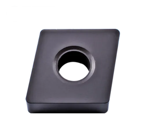
CNMA insertar
CNMA insert angle:0° Negative rake insert and no chipbreaker;
80° rhombic turning insert;
Primary workpiece material: Hard material; cast Iron; steel;
Primary workpiece material code: P; H; K
Insert holding method: Pin; Clamp;
Breaker application: Roughing, semi-finishing, finishing;
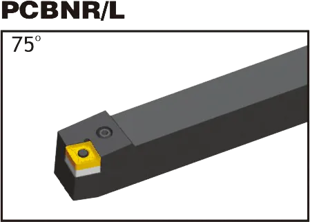
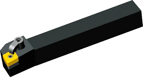
Matching cnma insert tool holder: PCBNR/L, PCLNR/L, MCLNR/L,MCBNR/L;
Grado: PVD y CVD;
Material : Carburo de Tungsteno;
CNMA insert tool holder


MCLNR/L
CNMA insert Introduction:
CNMA Carbide Inserts: The Essentials
- Shape: Rhombic (diamond) with an 80-degree included angle.
- Clearance Angle: 0 degrees
- Cutting Edges: Double-sided, offering two cutting edges per insert for cost-effectiveness.
- Chipbreaker Geometries: Diverse range of chipbreaker styles from various manufacturers are available. These are tailored to specific materials and machining operations (roughing, finishing, etc.).
- Key Uses: Primarily used for general turning operations and some facing work on a range of materials.
Common Materials CNMA Inserts are Used For
- Cast Iron: Suitable for many cast iron applications.
Advantages of CNMA Inserts
- Rentable: Due to their double-sided design, offering longer tool life per insert.
- Versatile: The range of grades and chipbreakers make them suitable for many machining applications.
- Strong Geometric Shape: The 80-degree diamond shape provides strength and rigidity for their size.
Important Considerations
- Match the Grade to Your Material: Choosing the right insert coating and substrate composition is crucial for optimal tool life and performance in the specific material you’re cutting.
- Select the Right Chipbreaker: The chipbreaker geometry significantly influences how chips are formed and broken. It should be chosen based on the material and type of machining operation.
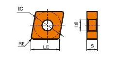
CNMA Insert Dimensions (ISO)
| TYPE | CNMA INSERT DIAMENTIONS(mm) | ||||
|---|---|---|---|---|---|
| LE | IC | S | DI | RE | |
| CNMA120404 | 12.9 | 12.7 | 4.76 | 5.16 | 0.4 |
| CNMA120408 | 12.9 | 12.7 | 4.76 | 5.16 | 0.8 |
| CNMA120412 | 12.9 | 12.7 | 4.76 | 5.16 | 1.2 |
| CNMA120416 | 12.9 | 12.7 | 4.76 | 5.16 | 1.6 |
| CNMA160608 | 16.1 | 15.875 | 6.35 | 6.35 | 0.8 |
| CNMA160612 | 16.1 | 15.875 | 6.35 | 6.35 | 1.2 |
| CNMA160616 | 16.1 | 15.875 | 6.35 | 6.35 | 1.6 |
| CNMA190612 | 19.3 | 19.05 | 6.35 | 7.94 | 1.2 |
| CNMA190616 | 19.3 | 19.05 | 6.35 | 7.94 | 1.6 |
Example: CNMA 120408
- 12: Inscribed Circle (IC) of 12.7mm (approx. 0.5 inches)
- 04: Thickness of 4.76mm (approx. 0.187 inches)
- 08: Corner radius of 0.8mm (approx. 0.031 inches)
Key Dimensions
Inscribed Circle (IC): The diameter of the largest circle that fits within the insert. Common IC sizes include:
- 12.7mm (0.5″)
- 16mm (0.63″)
- 19.05mm (0.75″)
Thickness: Impacts insert strength and the number of usable cutting edges. Common thicknesses include:
- 3.18mm (0.125″)
- 4.76mm (0.187″)
- 6.35mm (0.25″)
Corner Radius: Affects surface finish and strength at the cutting edge. Common sizes include:
- 0.4mm (0.016″)
- 0.8mm (0.031″)
- 1.2mm (0.047″)
La ciencia de las plaquitas de metal duro: Cómo se fabrican y por qué son tan resistentes
Las plaquitas de metal duro son unas de las herramientas de corte más versátiles y duraderas que existen. Pero, ¿cómo se fabrican? ¿Y qué las hace tan resistentes? En este vídeo, exploraremos la ciencia que hay detrás de las plaquitas de metal duro, desde las propiedades del carburo de tungsteno hasta el proceso de fabricación.
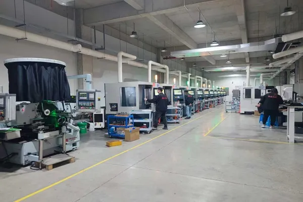
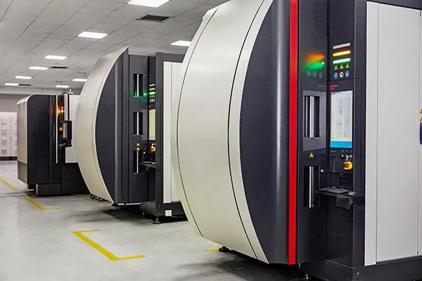
Nuestra capacidad de producción