SDMT120512 and SDMT150512 Milling Inserts
Compare SDMT120512 and SDMT150512 carbide milling inserts by insert dimensions, cutter compatibility and clamping hardware. This page combines the insert size platforms with the attached ASRF shell-cutter and ASRF12 shank-cutter parameter ranges for practical model selection.
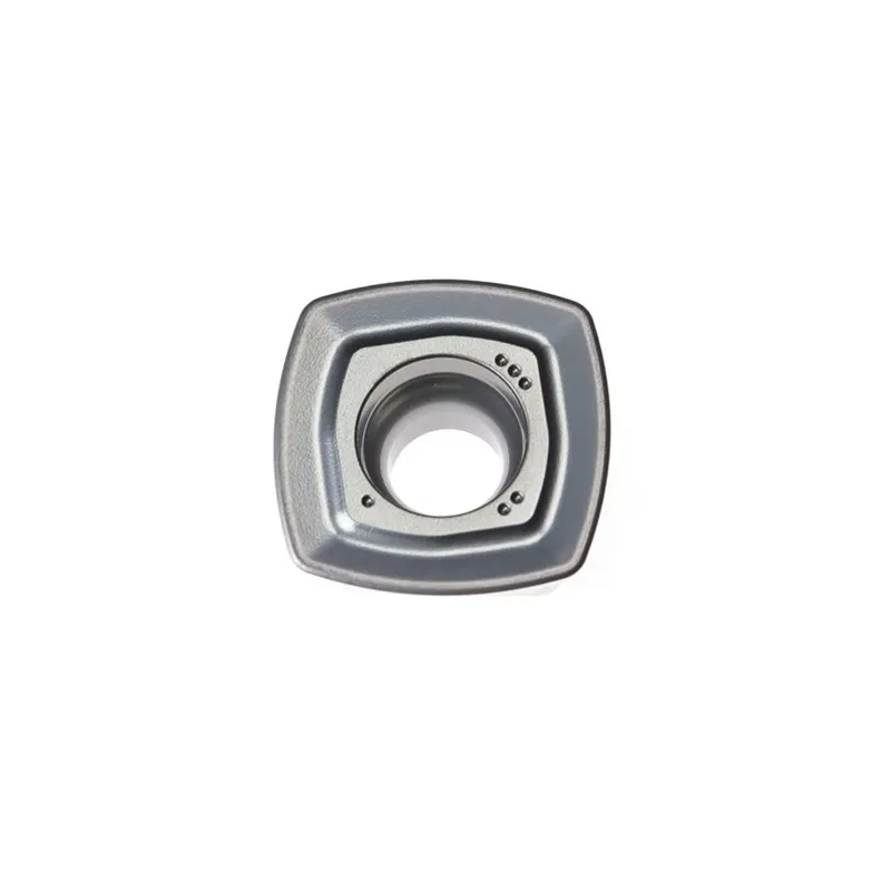
How to Read an SDMT Insert Designation
SDMT is a standard milling-insert family code. The letter block identifies the insert form, and the following number block identifies the size platform. Keep the full insert designation when matching a replacement to an existing cutter.
For this page, the two main size platforms are SDMT120512 and SDMT150512. Even though they share a similar family name, they use different core dimensions and are applied in different ASRF cutter ranges in the attached cutter-parameter references.
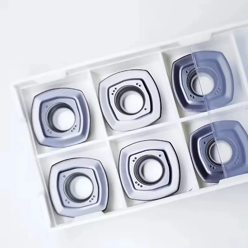
SDMT120512 and SDMT150512 Insert Specifications
The insert dimensions below are the core ordering values for the two SDMT platforms discussed on this page. Match the size platform first, then confirm the cutter-body model and the associated hardware.
Dimension Guide
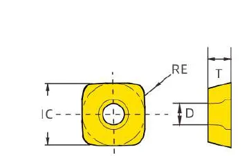
The technical drawing in the first screen shows the SDMT dimensional callouts. Use the following keys with the size table to confirm the exact insert platform before ordering.
| Insert Model | IC (mm) | T (mm) | D (mm) | RE (mm) | Typical Cutter Platform | Typical Hardware |
|---|---|---|---|---|---|---|
| SDMT120512 | 12.70 | 5.56 | 4.40 | 1.20 | ASRF12 shell cutter and ASRF12 shank-cutter range | M4×9 screw / T15 wrench |
| SDMT150512 | 15.88 | 5.56 | 5.50 | 1.20 | ASRF15 shell-cutter range | M5×12 screw / T20 wrench |
Typical Grade Selection Direction
Grade availability can differ by supplier and final SKU. Use the workpiece material, interruption level and cutter platform to confirm the final insert plus grade combination.
Toughness-oriented direction for general steel and interrupted milling conditions where edge reliability is important.
Balanced direction for common steel and stainless-steel milling where stable cutting and moderate wear resistance are required.
Wear-resistance direction for stable general milling and selected cast-iron conditions.
Actual grade availability must be confirmed against the complete SDMT insert code and current stock range.
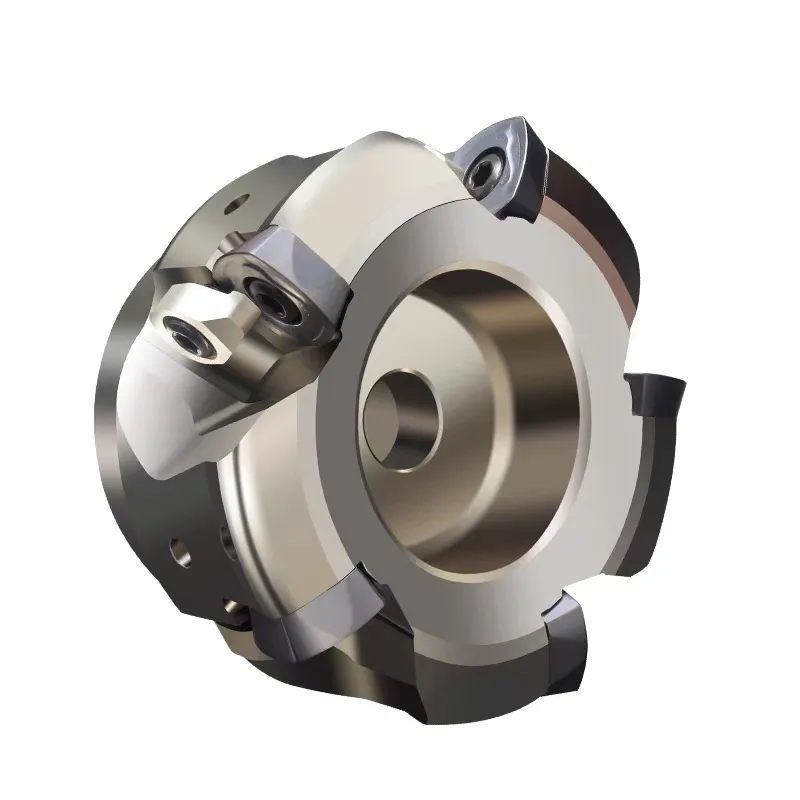
ASRF Shell Cutters for SDMT120512 and SDMT150512
The attached shell-cutter reference shows two SDMT cutter ranges: an ASRF12 range using SDMT120512, and an ASRF15 range using SDMT150512. Hardware also changes between the two size platforms.
| Cutter Model | Diameter D (mm) | Bore d (mm) | Teeth T | Insert | Screw | Wrench |
|---|---|---|---|---|---|---|
| ASRF12-50-22-4T | 50 | 22 | 4 | SDMT120512 | M4×9 | T15 |
| ASRF12-63-22-4T | 63 | 22 | 4 | SDMT120512 | M4×9 | T15 |
| ASRF12-63-22-5T | 63 | 22 | 5 | SDMT120512 | M4×9 | T15 |
| ASRF15-50-22-3T | 50 | 22 | 3 | SDMT150512 | M5×12 | T20 |
| ASRF15-63-22-4T | 63 | 22 | 4 | SDMT150512 | M5×12 | T20 |
| ASRF15-80-27-5T | 80 | 27 | 5 | SDMT150512 | M5×12 | T20 |
| ASRF15-100-32-5T | 100 | 32 | 5 | SDMT150512 | M5×12 | T20 |
| ASRF15-63-25.4-4T | 63 | 25.4 | 4 | SDMT150512 | M5×12 | T20 |
| ASRF15-80-25.4-5T | 80 | 25.4 | 5 | SDMT150512 | M5×12 | T20 |
ASRF12 Shank Cutter Models
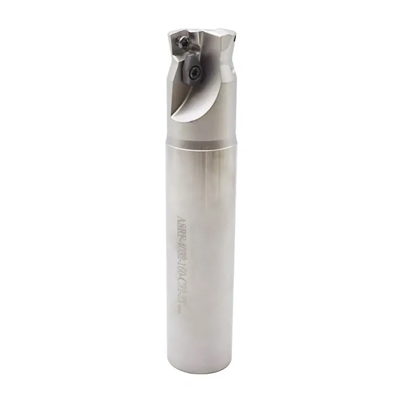
The attached shank-cutter parameter reference shows the ASRF12 shank range by cutter diameter, shank diameter and overall length. These models provide the practical cutter-body options associated with the SDMT 12 platform in the supplied attachment.
| Shank Cutter Model | Cutter Diameter (mm) | Shank Diameter (mm) | Total Length (mm) | Platform |
|---|---|---|---|---|
| ASRF12-32-160-C32 | 32 | 32 | 160 | ASRF12 / SDMT12 |
| ASRF12-32-200-C32 | 32 | 32 | 200 | ASRF12 / SDMT12 |
| ASRF12-33-160-C32 | 33 | 32 | 160 | ASRF12 / SDMT12 |
| ASRF12-33-200-C32 | 33 | 32 | 200 | ASRF12 / SDMT12 |
| ASRF12-33-250-C32 | 33 | 32 | 250 | ASRF12 / SDMT12 |
| ASRF12-35-160-C32 | 35 | 32 | 160 | ASRF12 / SDMT12 |
| ASRF12-35-200-C32 | 35 | 32 | 200 | ASRF12 / SDMT12 |
| ASRF12-35-250-C32 | 35 | 32 | 250 | ASRF12 / SDMT12 |
Why Customers Search for SDMT Inserts
SDMT inserts are often selected around complete cutter platforms rather than by insert dimensions alone. The attached ASRF shell-cutter and shank-cutter references show why screw size, wrench size and body platform matter in addition to the insert code.
SDMT120512 Platform
Matched in the attachment to ASRF12 shell cutters and the ASRF12 shank-cutter range.
SDMT150512 Platform
Matched in the attachment to the ASRF15 shell-cutter range with larger hardware.
Different Hardware
Platform 12 uses M4×9 and T15, while platform 15 uses M5×12 and T20.
Model-by-Model Matching
Body size, bore, tooth count and shank code must all be checked before ordering.
Typical SDMT Milling Applications
Application direction depends on the exact cutter body, insert grade, machine rigidity and workpiece material. The following use-cases are general product-positioning directions for the SDMT family.
Face Milling
Use SDMT inserts in compatible shell-type face mills for general milling and surface generation.
General Rough Milling
Suitable for practical roughing and semi-roughing in stable cutter-body platforms.
Shank-Cutter Milling
Use the ASRF12 shank-cutter range when the required cutter diameter and overhang are specified.
Platform-Based Replacement
Replace worn inserts by matching the full insert code and the exact ASRF cutter-body model.
How to Choose an SDMT Insert and Cutter Match
SDMT Milling Insert FAQ
What is the difference between SDMT120512 and SDMT150512?
Which shell cutter uses SDMT120512?
Which shell cutter uses SDMT150512?
What are the ASRF12 shank-cutter options shown on this page?
Can I replace any square insert with an SDMT insert?
Request SDMT Insert Pricing
Send the complete insert and cutter details so the size platform, cutter-body match and hardware can be checked before quotation.