SOMT High-Feed Milling Inserts
Compare SOMT100420ER-GM, SOMT140520ER-GM and SOMT140520ER-LD carbide milling inserts by dimensions, geometry and grade options. Match SOMT100420 to verified MFH10 and MFH large-depth cutter systems, and confirm the complete dedicated cutter designation before selecting a SOMT140520 insert.
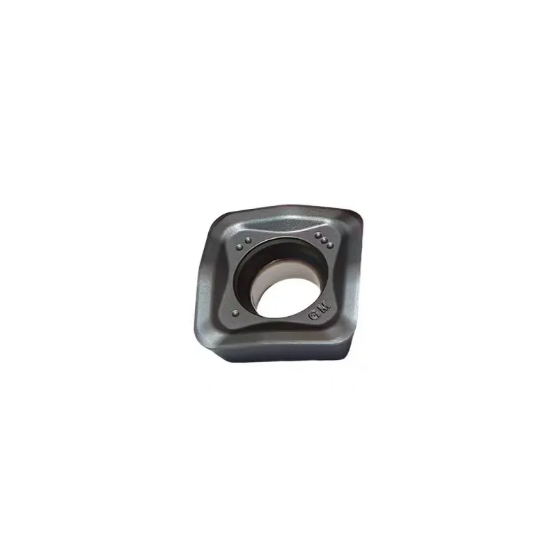

SOMT100420 and SOMT140520 Product Range
The 1004 and 1405 sizes use different dimensions, hole diameters and cutter pockets. The GM and LD suffixes also identify different cutting geometries.
1004 General High-Feed Geometry
IC 10.3 mm, thickness 4.58 mm and hole diameter 4.6 mm. Used with MFH10 and other compatible SOMT10 cutter bodies.
1405 General High-Feed Geometry
IC 14.14 mm, thickness 5.56 mm and hole diameter 5.8 mm. The widest grade selection in this product group.
1405 Large-Depth Geometry
Catalogue IC is 14.26 mm. Thickness, hole diameter and corner radius match the listed 1405 GM values, while LD remains a separate manufacturer geometry code.
What Is a SOMT High-Feed Milling Insert?
SOMT is a square positive-relief milling insert family used in compatible high-feed and large-depth milling cutter systems.
The complete designation identifies the size, 2.0 mm corner radius, right-hand edge direction and the manufacturer-specific GM or LD geometry. Milling SOMT inserts must be matched by the complete code because visually similar drilling inserts and other SOMT platforms can use different dimensions, edge forms and tool-body pockets.
SOMT Milling Insert Specifications
Compare IC, thickness, mounting-hole diameter, corner radius, relief angle, geometry and model-specific grade options.
Dimension Guide
Use the technical drawing in the first screen as the visual reference, then verify every catalogue value against the complete insert and cutter designation.
| Complete Designation | IC (mm) | T (mm) | D (mm) | RE (mm) | Relief | Geometry | Grade Options | Cutter Direction |
|---|---|---|---|---|---|---|---|---|
| SOMT100420ER-GM | 10.3 | 4.58 | 4.6 | 2.0 | 16° | GM | D530D570D580 | MFH10 / SOMT10 MFH systems |
| SOMT140520ER-GM | 14.14 | 5.56 | 5.8 | 2.0 | 16° | GM | D530D570D580D7320 | dedicated SOMT14 / SOMT14 MFH systems |
| SOMT140520ER-LD | 14.26 | 5.56 | 5.8 | 2.0 | 16° | LD | D530D570D580 | dedicated SOMT14 / SOMT14 large-depth systems |
GM vs LD Geometry
GM and LD are separate manufacturer geometry codes. Use them only with a cutter body and application data that explicitly support the complete insert designation.
General High-Feed Direction
- General-purpose direction within the listed SOMT high-feed range.
- Ramping, helical interpolation and plunging depend on the exact cutter-body design.
- Confirm maximum depth and entry capability from the cutter documentation.
Large-Depth Direction
- Separate geometry direction for larger-depth roughing applications.
- Do not substitute it for GM solely because thickness and hole diameter are similar.
- Confirm maximum depth, entry method and pocket compatibility from the exact cutter documentation.
SOMT Grade Options by Workpiece Material
First confirm that the grade is listed for the exact SOMT model, then match the grade direction to material, machining stability, coolant and wear mode.
Steel and cast-iron direction where toughness and interrupted-cut reliability are important.
General steel and stainless-steel direction, including stable and lighter finishing loads.
Steel and cast-iron direction for selected stable machining and wear-resistance requirements.
General-purpose steel, stainless and cast-iron direction, available only on SOMT140520ER-GM.
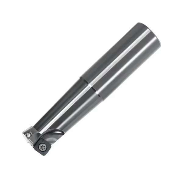 MFH10 Cutter PlatformCompact verified cutter direction for SOMT100420ER-GM
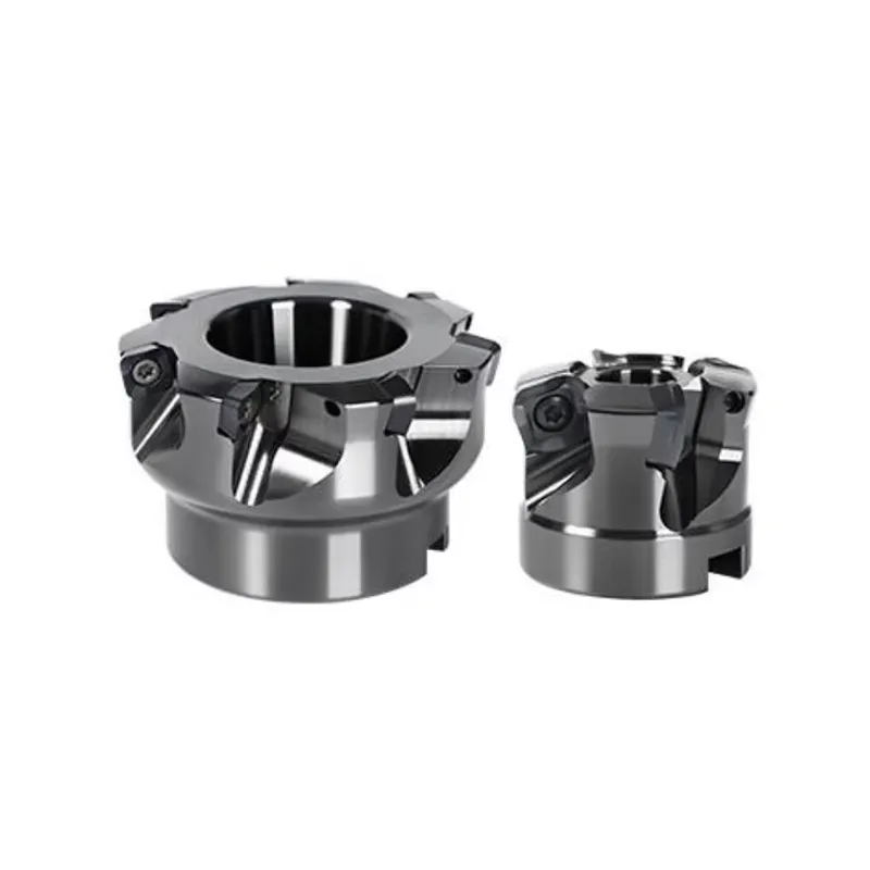 MFH Large-Depth CuttersVerified SOMT100420 holder direction in the supplied cutter catalogue
Match SOMT100420 Inserts to MFH10 and MFH Cutters
The supplied cutter catalogues clearly support SOMT100420 in MFH10 and MFH large-depth systems. For SOMT140520ER-GM or SOMT140520ER-LD, confirm the complete dedicated cutter-body designation and pocket drawing before publishing a compatibility claim.
MFH Large-Depth Holder Models
| Cutter Model | Teeth | Cutter Ø (mm) | Shank Ø (mm) | Total Length (mm) | Blade Length (mm) | Insert Platform |
|---|---|---|---|---|---|---|
| MFH 25-S25-10-2T-160 | 2 | 25 | 25 | 160 | 35 | SOMT100420 |
| MFH 25-S25-10-2T-200 | 2 | 25 | 25 | 200 | 40 | SOMT100420 |
| MFH 28-S25-10-2T-160 | 2 | 28 | 25 | 160 | 35 | SOMT100420 |
| MFH 28-S25-10-2T-200 | 2 | 28 | 25 | 200 | 40 | SOMT100420 |
| MFH 30-S25-10-2T-160 | 2 | 30 | 25 | 160 | 35 | SOMT100420 |
| MFH 30-S25-10-2T-200 | 2 | 30 | 25 | 200 | 40 | SOMT100420 |
| MFH 32-S32-10-3T-160 | 3 | 32 | 32 | 160 | 35 | SOMT100420 |
| MFH 32-S32-10-3T-200 | 3 | 32 | 32 | 200 | 40 | SOMT100420 |
| MFH 35-S32-10-3T-160 | 3 | 35 | 32 | 160 | 35 | SOMT100420 |
| MFH 35-S32-10-3T-200 | 3 | 35 | 32 | 200 | 40 | SOMT100420 |
| MFH 40-S32-10-4T-160 | 4 | 40 | 32 | 160 | 35 | SOMT100420 |
| MFH 40-S32-10-4T-200 | 4 | 40 | 32 | 200 | 40 | SOMT100420 |
Four Usable Cutting Corners
The square SOMT milling design provides four indexable cutting corners. Correct indexing and stable pocket seating allow each corner to be used before the insert is replaced.
SOMT Milling Applications
Actual capability depends on the complete cutter body, GM or LD geometry, carbide grade, machine rigidity and workpiece setup.
High-Feed Face Milling
General roughing direction for SOMT inserts used in compatible high-feed cutter systems.
High-feed milling toolsLarge-Depth Roughing
LD geometry direction for larger axial engagement when the exact cutter documentation supports it.
Pocket and Mould Roughing
For suitable GM cutter bodies where chip evacuation, radial engagement and remaining stock are controlled.
Ramping, Helical and Plunging
Use only with a cutter body specifically designed and documented for axial or oblique entry.
SOMT Milling Insert FAQ
Are SOMT milling inserts interchangeable with SOMT U-drill inserts?
What is the difference between SOMT140520ER-GM and SOMT140520ER-LD?
Which cutter uses SOMT100420?
Can every SOMT cutter perform ramping, helical interpolation or plunging?
How to Choose a SOMT Milling Insert
Request SOMT Milling Insert Pricing and Cutter Compatibility Review
Provide the complete insert and milling cutter details so the correct size, geometry, carbide grade and pocket fit can be checked.