Как изготавливаются твердосплавные вставки: Исчерпывающее руководство по производству
Твердосплавные пластины - важнейшие компоненты современного производства, которые ценятся за исключительную твердость, износостойкость и способность сохранять остроту режущих кромок в экстремальных условиях. Но задумывались ли вы когда-нибудь о том, как создаются эти важнейшие инструменты? В этом подробном руководстве мы рассмотрим сложный процесс изготовления твердосплавных пластин - от сырья до готовой продукции.
Введение: Мир твердосплавных пластин
Твердосплавные пластины произвели революцию в металлообрабатывающей промышленности, обеспечив более высокую скорость резания, улучшенную чистоту поверхности и увеличенный срок службы инструмента. Чтобы понять их важность, мы должны сначала вникнуть в сложный производственный процесс, который воплощает в жизнь эти высокопроизводительные режущие инструменты. Так как же изготавливаются твердосплавные пластины? Давайте исследуем этот увлекательный путь от порошка до точности.
Сырьевые материалы: Строительные блоки твердосплавных вставок
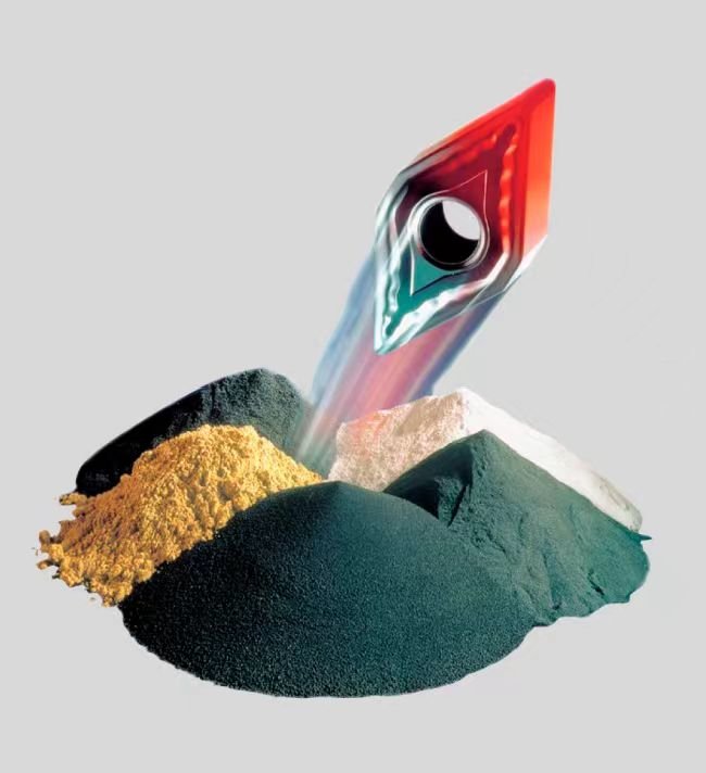
Прежде чем ответить на вопрос, как изготавливаются твердосплавные вставки, необходимо разобраться в материалах. Основными компонентами, используемыми при изготовлении твердосплавных вставок, являются:
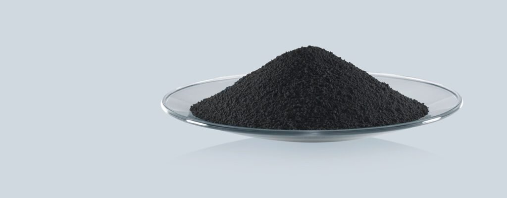
- Порошок карбида вольфрама: это основной компонент, обеспечивающий твердость и износостойкость вставки.
- Кобальтовый порошок: Действует как связующее вещество, удерживая частицы карбида вольфрама вместе.
- Дополнительно карбиды: Такие как карбид титана или карбид тантала, могут быть добавлены для улучшения специфических свойств.
Качество и соотношение этих сырьевых материалов существенно влияют на конечные характеристики твердосплавной вставки.
Процесс производства: Как изготавливаются твердосплавные вставки шаг за шагом
Теперь давайте углубимся в суть нашей темы: как изготавливаются твердосплавные вставки? Этот процесс включает в себя несколько важнейших этапов, каждый из которых вносит свой вклад в конечные свойства и производительность пластины. Понимание этого процесса - ключ к пониманию сложности и точности, с которыми создаются эти высокопроизводительные режущие инструменты.
1. Подготовка порошка
Процесс изготовления твердосплавных вставок начинается с тщательного отбора и подготовки порошков.
- Выбор сырья: Приобретается карбид вольфрама и кобальтовые порошки высокой чистоты. Качество этих сырьевых материалов имеет решающее значение для конечных характеристик вставки.
- Анализ порошков: Порошки анализируются на гранулометрический состав, чистоту и химический состав.
- Взвешивание и дозирование: Точное количество порошков карбида вольфрама и кобальта взвешивается в соответствии с требуемыми техническими характеристиками. Содержание кобальта обычно варьируется от 6% до 30%, в зависимости от предполагаемого применения вставки.
- Внесение добавок: При необходимости на этом этапе добавляются дополнительные карбиды, такие как карбид титана или карбид тантала, для улучшения специфических свойств.
2. Смешивание и измельчение
Этот этап имеет решающее значение при изготовлении твердосплавных вставок, поскольку он определяет однородность конечного продукта.
- Первоначальное смешивание: Отмеренные порошки тщательно перемешиваются в V-блендере или турбулентном миксере для равномерного распределения всех компонентов.
- Шаровое измельчение: Затем смесь переносится в шаровую мельницу. В этом устройстве используются твердые, износостойкие шары (часто из карбида вольфрама) для дальнейшего смешивания и измельчения порошка.
- Мокрый помол: Для облегчения процесса измельчения и предотвращения окисления добавляется жидкая среда, обычно спирт.
- Продолжительность измельчения: Процесс измельчения может длиться от 24 до 72 часов, в зависимости от желаемого размера частиц и характеристик сорта.
- Уменьшение размера частиц: В процессе измельчения частицы порошка уменьшаются до субмикронных размеров, обычно от 0,5 до 5 микрометров.
- Сушка: После измельчения суспензия высушивается с помощью распылительной или вакуумной сушки для удаления жидкой среды.
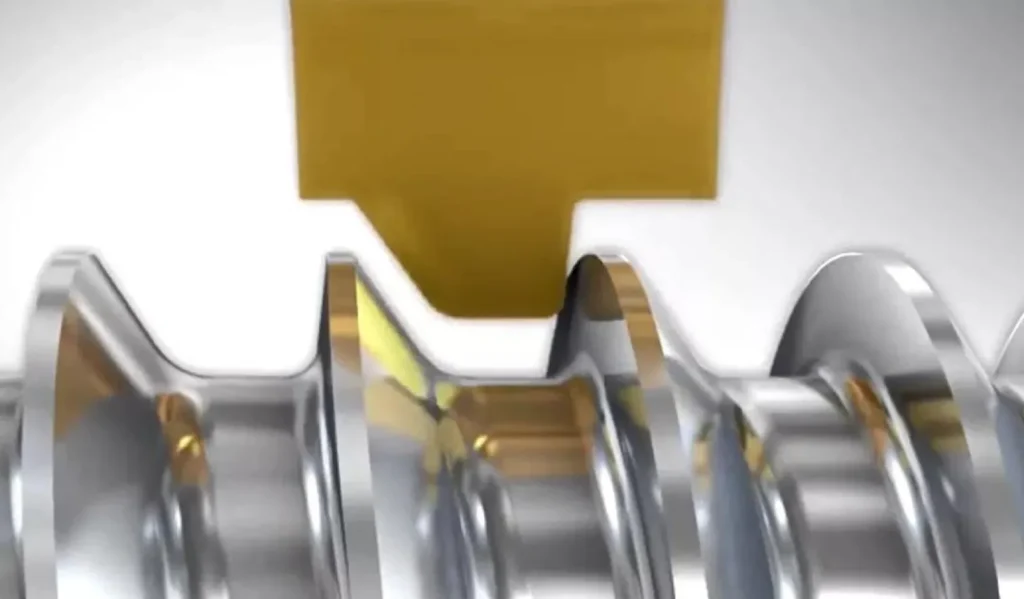
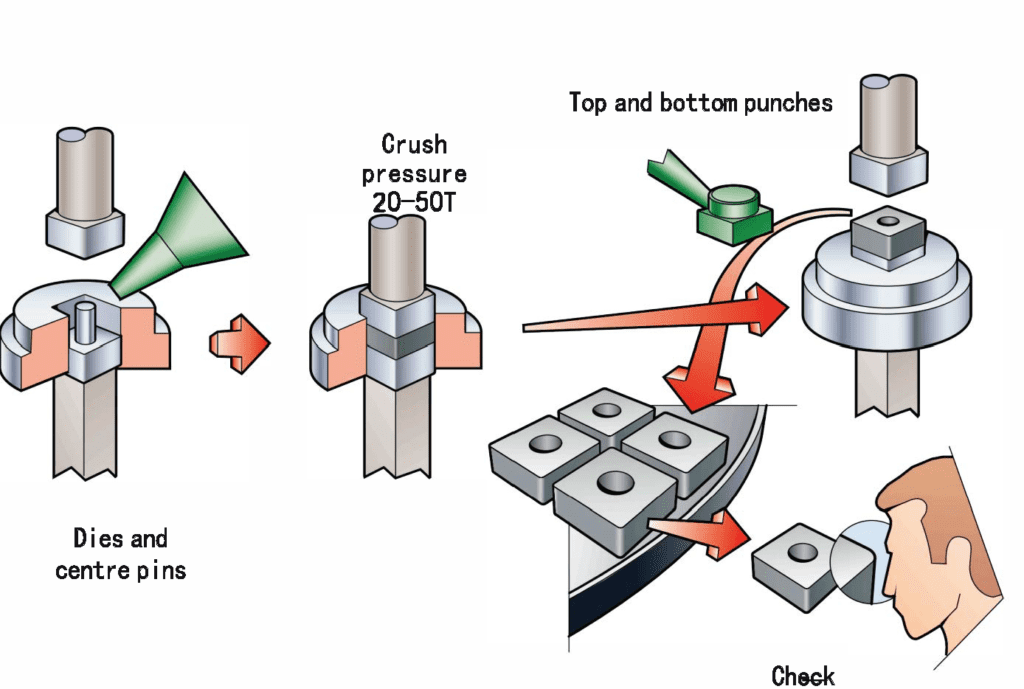
3. Прессование и формование
На следующем этапе изготовления твердосплавных вставок порошок формуется в нужную форму.
- Смазывание порошка: Небольшое количество органического связующего (часто парафина) добавляется в порошок для улучшения его текучести и сжимаемости.
- Подготовка штампа: Подготавливается штамп с формой желаемой вставки. Полость штампа часто немного увеличивается, чтобы учесть усадку во время спекания.
- Засыпка порошка: Подготовленная порошковая смесь аккуратно засыпается в полость штампа.
- Уплотнение: Порошок сжимается под высоким давлением, обычно от 10 до 30 тонн на квадратный дюйм, с помощью гидравлических или механических прессов.
- Формирование зеленого компакта: В результате получается "зеленый компакт", который имеет основную форму конечной вставки, но все еще относительно мягкий и хрупкий.
- Выброс: Зеленая компактная гильза аккуратно извлекается из матрицы.
4. Предварительное спекание (по желанию)
Некоторые производители включают этап предварительного спекания в процесс изготовления твердосплавных пластин.
- Низкотемпературный нагрев: Зеленые компакты нагреваются до температуры от 500°C до 900°C.
- Удаление связующего: В ходе этого процесса удаляется органическое связующее, использованное на этапе прессования.
- Повышение прочности: Предварительное спекание немного повышает прочность компакта, облегчая его обработку на последующих этапах.
5. Спекание
Спекание - важнейший этап изготовления твердосплавных вставок, превращающий хрупкую зеленую массу в плотную твердую твердосплавную вставку.
- Загрузка печи: Зеленые компакты (или предварительно спеченные детали) загружаются в печь для спекания.
- Контроль атмосферы: Атмосфера печи тщательно контролируется, часто используется вакуум или инертный газ, например аргон, для предотвращения окисления.
- Повышение температуры: Температура постепенно повышается примерно до 1400°C (около точки плавления кобальта).
- Период выдержки: Температура поддерживается в течение определенного периода времени, обычно 1-3 часа, что позволяет кобальту расплавиться и проникнуть между частицами карбида вольфрама.
- Жидкофазное спекание: Расплавленный кобальт действует как связующее вещество, заполняя промежутки между частицами карбида.
- Охлаждение: Печь медленно охлаждается, позволяя кобальту затвердеть и связать частицы карбида вместе.
- Усадка: Во время спекания вставка сжимается примерно на 17-25% за счет устранения пор и уплотнения структуры.
6. Горячее изостатическое прессование (HIP) (опция)
Некоторые высокопроизводительные пластины проходят дополнительный этап изготовления твердосплавных пластин.
- Среда высокого давления: Спеченные вставки помещаются в специальную камеру, заполненную инертным газом под очень высоким давлением (до 30 000 фунтов на квадратный дюйм).
- Повышенная температура: Камера нагревается до температуры, близкой к температуре спекания.
- Ликвидация пор: Сочетание высокого давления и температуры устраняет оставшуюся пористость, в результате чего образуется полностью плотная структура.
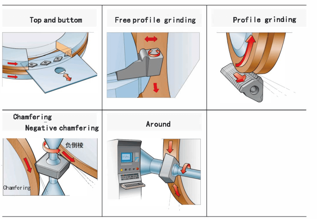
7. Финишная обработка и шлифовка
Последние этапы изготовления твердосплавных пластин включают в себя достижение точных размеров и геометрии, необходимых для оптимальной работы.
- Грубая шлифовка: Спеченные вставки шлифуются для удаления всех дефектов поверхности и достижения основной формы.
- Прецизионное шлифование: Высокоточные шлифовальные станки используются для создания точных размеров, режущих кромок и стружколомателей, необходимых для конкретного типа пластин.
- Подготовка кромок: Режущие кромки могут быть отточены или им может быть придана особая микрогеометрия для повышения их производительности и долговечности.
- Финишная обработка поверхности: некоторые пластины подвергаются дополнительной обработке поверхности, например, полировке, чтобы улучшить сход стружки или уменьшить образование наростов на кромке.
8. Контроль качества
На протяжении всего процесса изготовления твердосплавных пластин осуществляется контроль качества:
- Проверка размеров: Проводятся точные измерения, чтобы убедиться, что вставка соответствует требуемым характеристикам.
- Испытание на твердость: Твердость вставки проверяется на соответствие требованиям марки.
- Анализ микроструктуры: Образцы исследуются под микроскопом для проверки зерновой структуры и состава.
- Тестирование производительности: Некоторые пластины из каждой партии могут проходить испытания на резку для проверки их производительности.
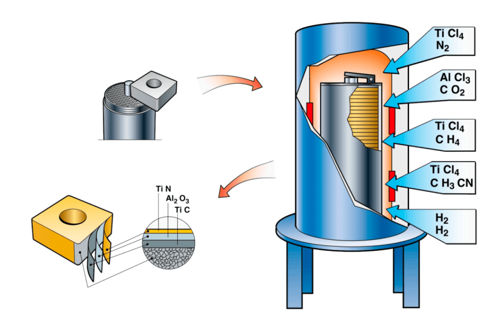
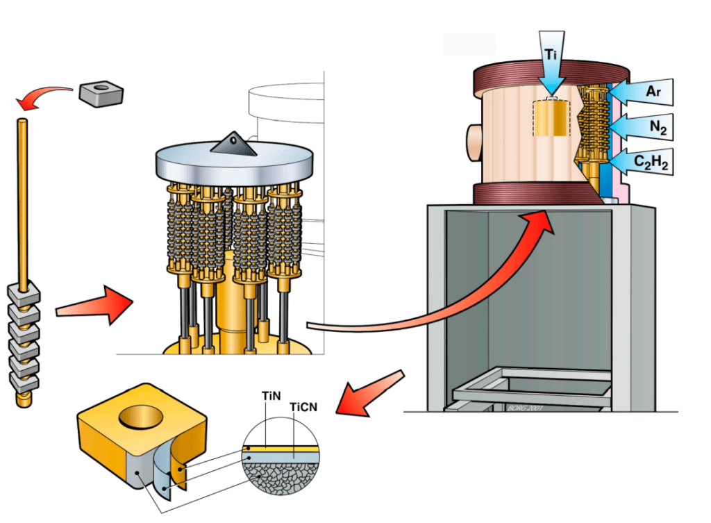
9. Покрытие (опционально)
Многие твердосплавные вставки проходят дополнительный этап производственного процесса: нанесение покрытия. Этот этап повышает износостойкость, термостойкость и общую производительность пластины.
- Подготовка поверхности: Вставки очищаются и иногда предварительно обрабатываются для обеспечения хорошей адгезии покрытия.
- Нанесение покрытия: В зависимости от желаемых свойств, покрытия наносятся такими методами, как:
- Химическое осаждение из паровой фазы (CVD): Для более толстых, износостойких покрытий
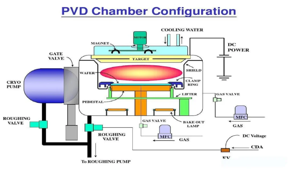
- Физическое осаждение из паровой фазы (PVD): Для острых кромок и более прочных покрытий
- Многослойные покрытия: Многие современные вставки имеют несколько слоев различных материалов покрытия для оптимизации работы.
- Обработка после нанесения покрытия: Некоторые вставки с покрытием подвергаются дополнительной обработке, например, хонингованию или полировке, чтобы улучшить поверхность покрытия.
Подробное описание процесса изготовления твердосплавных пластин подчеркивает сложность и точность создания этих важнейших режущих инструментов. Каждый этап вносит свой вклад в конечные свойства пластины, гарантируя, что она сможет выдержать сложные условия современной обработки.
Техника нанесения покрытий: Повышение эффективности твердосплавных пластин
Многие твердосплавные пластины в процессе производства проходят дополнительный этап - нанесение покрытия. Но что такое покрытие на твердосплавных вставках и зачем оно наносится?
Покрытия - это тонкие слои твердых материалов, которые наносятся на поверхность твердосплавной вставки для улучшения ее характеристик. К распространенным материалам покрытий относятся:
- Нитрид титана (TiN)
- Карбонитрид титана (TiCN)
- Оксид алюминия (Al2O3)
- Нитрид титана и алюминия (TiAlN)
Эти покрытия обычно наносятся такими методами, как:
- Химическое осаждение из паровой фазы (CVD)
- Физическое осаждение из паровой фазы (PVD)
Процесс нанесения покрытия - важнейшая часть процесса изготовления твердосплавных пластин для многих высокопроизводительных применений. Он позволяет значительно повысить износостойкость, снизить трение и продлить срок службы инструмента.
Градации и классификация твердосплавных пластин
Понимание того, как изготавливаются твердосплавные пластины, также предполагает знание различных сортов. Система классификации твердосплавных пластин имеет решающее значение для выбора подходящего инструмента для конкретных видов обработки. Давайте углубимся в этот сложный, но важный аспект технологии твердосплавных пластин.
Система классификации ISO
Международная организация по стандартизации (ISO) установила общепринятую систему классификации твердосплавных пластин. В этой системе используются буквы и цифры для обозначения характеристик и назначения пластины:
- Группы приложений (письма):
- P: Для обработки стали (синий цветовой код)
- M: Для обработки нержавеющей стали (желтый цветовой код)
- K: Для обработки чугуна (красный цветовой код)
- N: Для обработки цветных металлов (зеленый цветовой код)
- S: Для обработки жаропрочных суперсплавов и титана (коричневый цветовой код)
- H: Для обработки закаленных материалов (серый цветовой код)
- Шкала твердости и жесткости (цифры):
- Диапазон от 01 до 50
- Более низкие номера обозначают более твердые, износостойкие марки (например, P01, K10).
- Более высокие цифры указывают на более жесткие и ударопрочные марки (например, P50, M40).
Специфические характеристики сорта
В каждой группе приложений, марки твердосплавных пластин далее различаются по составу и свойствам:
- C Grades (чугун):
- Пример: K10 - мелкозернистая марка WC-Co для высокоскоростной финишной обработки чугуна
- Пример: K20 - среднезернистая марка для обработки чугуна общего назначения
- Степени P (сталь):
- Пример: P01 - ультрамелкозернистая марка для высокоскоростной обработки стали
- Пример: P25 - среднезернистая марка с хорошим балансом износостойкости и вязкости для общей обработки стали
- M Grades (нержавеющая сталь):
- Пример: M10 - мелкозернистая марка для высокоскоростной обработки нержавеющей стали
- Пример: M30 - более жесткая марка для прерывистой резки нержавеющей стали
- Специализированные классы:
- Марки N для цветных материалов (например, алюминия, меди)
- марки S для жаропрочных сверхпрочных сплавов (например, инконель, хастеллой)
- Марки H для закаленных сталей и других твердых материалов
Микроструктура и состав
Градация твердосплавных пластин напрямую зависит от способа их изготовления. Ключевыми факторами являются:
- Размер зерна:
- Нанозерно: <0,1 мкм
- Субмикронные: 0,1-0,5 мкм
- Мелкозернистый: 0,5-1,0 мкм
- Среднезернистые: 1,0-2,5 мкм
- Крупнозернистый: >2,5 мкм
- Содержание кобальта:
- Обычно варьируется от 6% до 30%
- Более высокое содержание кобальта повышает прочность, но снижает твердость
- Дополнительные твердые сплавы:
- Карбид титана (TiC): Повышает износостойкость кратера
- Карбид тантала (TaC): Повышает высокотемпературную стабильность
- Карбид ниобия (NbC): Повышает прочность кромок
Выбор правильного класса
При выборе подходящей марки твердосплавной пластины необходимо учитывать несколько факторов:
- Материал заготовки: Подберите класс вставки в соответствии с обрабатываемым материалом.
- Условия резания: Учитывайте такие факторы, как скорость резания, подача и глубина резания.
- Стабильность машины: Более устойчивые установки могут использовать более твердые сорта; менее устойчивые могут требовать более жестких сортов.
- Требования к чистоте поверхности: Более мелкозернистые сорта обычно дают лучшую поверхность.
- Ожидаемая стойкость инструмента: Более твердые сорта обычно обеспечивают более длительный срок службы инструмента при непрерывном резании.
Передовые разработки
По мере того как производители продолжают совершенствовать способы изготовления твердосплавных вставок, разрабатываются новые марки для решения конкретных задач:
- Многослойные гранулы: Сочетание различных составов карбида в слоях для оптимизации характеристик.
- Функционально-градиентные вставки: Варьирование состава от сердцевины к поверхности для достижения идеального баланса прочности и износостойкости.
- Нанокомпозитные гранулы: Включение наноразмерных частиц для улучшения специфических свойств.
Понимание этих марок и классификаций имеет решающее значение для оптимизации процессов обработки. Выбрав правильную марку, производители могут значительно повысить производительность, срок службы инструмента и качество деталей. Продолжая изучать процесс изготовления твердосплавных пластин, становится ясно, что система классификации играет ключевую роль в воплощении производственного процесса в практичные инструменты для конкретного применения.
Твердосплавные и керамические вставки: Сравнение
Пока мы сосредоточились на том, как изготавливаются твердосплавные вставки, стоит сравнить их с другим популярным вариантом - керамическими вставками.
Твердосплавные вставки:
- Повышенная прочность и ударопрочность
- Более широкий диапазон применения
- Низкая стоимость
Керамические вставки обеспечивают:
- Повышенная термостойкость
- Лучшая производительность при высоких скоростях резки
- Увеличение срока службы инструмента в некоторых областях применения
Выбор между твердым сплавом и керамикой зависит от конкретных требований к обработке и материала заготовки.
Понимание маркировки твердосплавных пластин
Чтобы узнать, как изготавливаются твердосплавные вставки, необходимо понять, как они маркируются. Маркировка твердосплавных вставок предоставляет важную информацию об их геометрии, размере и предполагаемом применении. Эти маркировки соответствуют стандартным системам, в первую очередь системе ISO (Международная организация по стандартизации), которая широко используется в промышленности. Давайте разберем эти маркировки, чтобы понять, что представляет собой каждый элемент.
Система номенклатуры ISO
В системе ISO используется ряд букв и цифр для описания характеристик вставки. Типичное обозначение ISO может выглядеть следующим образом:
CNMG 120408-PM 4325
Давайте шаг за шагом расшифруем эту маркировку:
- Форма вставки (1-я буква)
- C: 80° алмаз
- D: 55° бриллиант
- R: Круглый
- S: Квадрат
- Т: Треугольник
- V: 35° алмаз
- W: Тригон (3-сторонний)
- Угол рельефа (2-я буква)
- N: 0°
- P: 11°
- C: 7°
- E: 20°
- F: 25°
- O: 0° (для специальных применений)
- Класс толерантности (3-я буква)
- A: Ближайший допуск
- G: Средняя толерантность
- М: Более широкая толерантность
- Особенности вставки (4-я буква)
- G: Паз на лицевой стороне и отверстие с зенковкой
- N: Паз на лицевой стороне и отверстие без зенковки
- R: Круглое отверстие без зенковки
- T: Отверстие с зенковкой, без канавки
- Размер вставки (первый набор цифр)
- 12: Диаметр вписанной окружности или длина края (в мм)
- 04: Толщина вставки (в мм)
- Радиус угла (последние две цифры)
- 08: радиус угла 0,8 мм
- Стружкоотделитель и гравировка (-PM 4325)
- PM: Стиль прерывателя стружки (зависит от производителя)
- 4325: Обозначение марки (зависит от производителя)
Дополнительная маркировка
Помимо системы ISO, производители часто наносят дополнительную маркировку:
- Логотип бренда: Идентифицирует производителя.
- Класс материала: Часто имеют цветовую маркировку (например, синий - сталь, желтый - нержавеющая сталь).
- Тип покрытия: Может быть обозначен определенным цветом или маркировкой.
- Состояние режущей кромки: Символы могут обозначать заточенные или острые кромки.
- Индикаторы отверстий для СОЖ: Для пластин, предназначенных для сквозной подачи СОЖ.
Интерпретация специальных геометрий
Некоторые вставки имеют специальную геометрию, которая указана в их маркировке:
- Сбрасывающие вставки: Часто обозначаются буквой "W" в обозначении стружколомателя.
- Вставки с высокой подачей: Могут иметь обозначение 'HF' или аналогичное.
- Двусторонние вставки: Обозначаются определенными буквами в позиции характеристик вставки.
Коды конкретного производителя
Хотя система ISO обеспечивает стандартизированную базу, многие производители добавляют свои собственные коды, чтобы предоставить более конкретную информацию:
- Sandvik Coromant: Использует префикс "GC" для обозначения марки (например, GC4325).
- Kennametal: Использует префикс 'KC' для своих марок (например, KC5010).
- Искар: Часто включает "IC" в обозначение своей оценки (например, IC8150).
Понимание упаковки с вкладышами
На упаковке твердосплавных пластин часто содержится дополнительная ценная информация:
- Рекомендуемые параметры резки: Диапазоны скорости, подачи и глубины резания.
- Совместимость материалов: Символы или коды, указывающие на подходящие материалы заготовок.
- Номера партий: Для контроля качества и отслеживания.
- Рекомендации по хранению: Для сохранения качества вставки.
Важность в производственном процессе
Понимание этой маркировки важно не только для пользователей, но и для процесса изготовления твердосплавных пластин. Маркировка обычно наносится на последних этапах производства:
- Лазерная гравировка: Многие маркировки наносятся с помощью высокоточных систем лазерной гравировки.
- Цветовое кодирование: Некоторые производители наносят цветные точки или полосы для обозначения марки или совместимости материалов.
- Контроль качества: Точность маркировки проверяется в процессе окончательного контроля.
Советы по чтению маркировки твердосплавных пластин
- Всегда обращайтесь к каталогу или веб-сайту производителя для получения информации о системе кодирования.
- Обратите внимание на порядок маркировки, так как у разных производителей он может немного отличаться.
- Для работы с маленькими вставками используйте лупу или увеличительное стекло, так как разметка может быть очень мелкой.
- В случае сомнений проконсультируйтесь с производителем инструмента или специалистом по режущим инструментам.
- Имейте в виду, что некоторые специальные или заказные вставки могут не соответствовать стандартной системе ISO.
Понимание этой маркировки необходимо для выбора подходящей вставки для конкретной операции обработки. Оно позволяет быстро определить форму, размер, допуск и назначение пластины. Эти знания в сочетании с пониманием того, как изготавливаются твердосплавные пластины, позволяют машинистам и инженерам оптимизировать процессы резания для достижения максимальной эффективности и качества.
По мере развития производственных технологий могут появиться новые системы маркировки, позволяющие использовать более сложные геометрии пластин и современные материалы. Быть в курсе этих изменений крайне важно для всех, кто работает с режущими инструментами в современных производственных условиях.
Твердый сплав с покрытием и без покрытия: В чем разница?
Говоря о том, как изготавливаются твердосплавные пластины, важно отметить разницу между их разновидностями с покрытием и без него.
Твердосплавные вставки с покрытием:
- Повышенная износостойкость
- Более высокая скорость резки
- Более длительный срок службы инструмента
- Улучшенная обработка поверхности в некоторых случаях
Твердосплавные вставки без покрытия обеспечивают:
- Более острые режущие кромки
- Лучшая производительность при прерывистых сокращениях
- Низкая стоимость
- Пригодность для цветных материалов
Выбор между покрытием и без покрытия зависит от конкретной операции обработки и материала заготовки.
Твердый сплав против КНБ: твердость и применение
Изучая, как изготавливаются твердосплавные вставки, вы, возможно, зададитесь вопросом о других сверхтвердых материалах, таких как кубический нитрид бора (CBN). Является ли CBN более твердым, чем карбид?
Да, CBN тверже, чем твердый сплав. Однако твердосплавные пластины более широко распространены из-за их:
- Низкая стоимость
- Повышенная прочность
- Более широкий спектр применения
КНБ отлично справляется с обработкой закаленных сталей и чугуна, но он дороже и менее прочен, чем твердый сплав.
Определение твердосплавных вставок
Как узнать, является ли вставка твердосплавной? Вот некоторые характеристики:
- Тускло-серый цвет (для вставок без покрытия)
- Высокая плотность (на ощупь тяжелее, чем на вид)
- Магнитный (благодаря содержанию кобальта)
- Очень твердый (может поцарапать стекло)
Для вставок с покрытием цвет покрытия может быть разным (например, золотым для TiN, серым для TiCN).
Заключение: Будущее производства твердосплавных пластин
Понимание того, как изготавливаются твердосплавные вставки, крайне важно для всех, кто занимается механической обработкой. От тщательного отбора сырья до точного контроля производственного процесса - каждый шаг вносит свой вклад в конечные характеристики вставки.
Заглядывая в будущее, мы видим, что достижения в области материаловедения и производственных технологий обещают еще более совершенные твердосплавные вставки. Инновации в области нанозернистых карбидов, многослойных покрытий и специализированных микрогеометрий - вот лишь несколько областей, которые могут изменить способы изготовления твердосплавных вставок в ближайшие годы.
Разобравшись в тонкостях производства твердосплавных пластин, инженеры и машинисты смогут принимать более взвешенные решения, оптимизируя операции резки и расширяя границы возможного в области обработки металлов резанием.