
CNMMインサート
CNMM insert angle:0° Negative rake insert with a single-sided chipbreaker;
80°菱形旋回挿入;
Primary workpiece material: stainless steel, steel, brass, bronze, aluminium and cast iron;
Breaker application: Rough, heavy, semi-finshing;
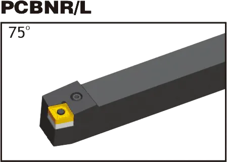
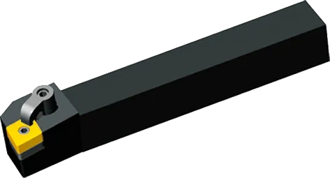
Matching TurningTool Holder: PCBNR/L, PCLNR/L, MCLNR/L,MCBNR/L;
Grade: CVD;
Material : Tungsten Carbide
CNMM Insert Specifications
Heavy and semi-heavy machining require chip breakers designed for the task. Wide chip breakers optimize chip control at large depths of cut and high feeds. Cutting edge strength is maximized with a flat, negative land design. Conversely, finishing operations benefit from smaller chip breakers to facilitate chip breaking due to reduced cutting force. In finishing, prioritize cutting edge sharpness with a positive land and small edge honing. CNMM insert excel in roughing applications.
CNMM insert tool holder


mclnr/l
CNMM insert Introduction
1. Dimensions
- 形: 80度の角度が含まれている菱形(ダイヤモンド)。
- クリアランス角度: Negative (typically in the range of -5 to -7 degrees).
- 許容範囲: Medium (‘M’) is typical, but other tolerances may exist for specialized needs.
- 刻まれた円(IC): Determines the overall insert size (common: 12.7mm, 16mm).
- 厚さ: Impacts strength and cutting edge count (common: 4.76mm, 6.35mm).
- コーナー半径: Affects strength and surface finish (common: 0.4mm, 0.8mm, 1.2mm).
2. Chipbreaker Geometries
- Hugely Important: Chipbreakers shape how chips form and break, ensuring efficient chip flow, tool protection, and workpiece finish.
- Manufacturer-Specific: Chipbreaker designations are coded into the CNMM code (the “MM”). Refer to manufacturer catalogs for the specifics.
- Match to Operation: Consider:
- ワーク資料
- Depth of cut (light vs. heavy)
- Desired finish
3. Hole Configuration
- Central Hole: For secure clamping on toolholders.
- Hole-less: Rely on alternative clamping mechanisms.
- Toolholder Compatibility: Essential to match the insert’s hole configuration to your toolholder.
4. Coating and Substrate
- コーティング: Common types include TiN, TiAlN, CVD, and PVD. Each offers different wear resistance, thermal properties, and suitability for various materials.
- Substrate: The base carbide material the coating is applied to. Compositions vary, offering toughness vs. wear resistance trade-offs.
- Application-Specific: The right grade is crucial for optimal performance and tool life.
CNMM Insert Dimensions (ISO)
| ISO指定 | 内接円 (IC) | 厚さ | コーナー半径 |
|---|---|---|---|
| CNMM 120404 | 12.7mm (0.5") | 4.76mm (0.187") | 0.4mm (0.016") |
| CNMM 120408 | 12.7mm (0.5") | 4.76mm (0.187") | 0.8mm (0.031") |
| CNMM 120412 | 12.7mm (0.5") | 4.76mm (0.187") | 1.2mm (0.047") |
| CNMM 160608 | 16mm (0.63") | 6.35mm (0.25") | 0.8mm (0.031") |
Example: CNMM 120408
- Rhombic (diamond) shape with an 80-degree included angle
- Negative clearance angle
- Manufacturer-specific details within the “MM” designation
- 12mm inscribed circle diameter (approx. 0.47″ インチで)
- 4mm thick (approx. 0.157″ インチで)
- 0ノーズ半径 0.8mm (約 0.031″ インチで)
The Science Behind Carbide Inserts: How They're Made and Why They're So Strong
超硬インサートは、入手可能な切削工具の中で最も多用途で耐久性のあるものの一部です。しかし、それらはどのように作られるのでしょうか?そして何が彼らをそんなに強いのでしょうか?このビデオでは、炭化タングステンの特性から製造プロセスまで、超硬インサートの背後にある科学を探求します。
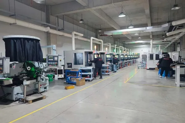
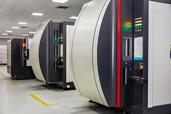
当社の生産能力

