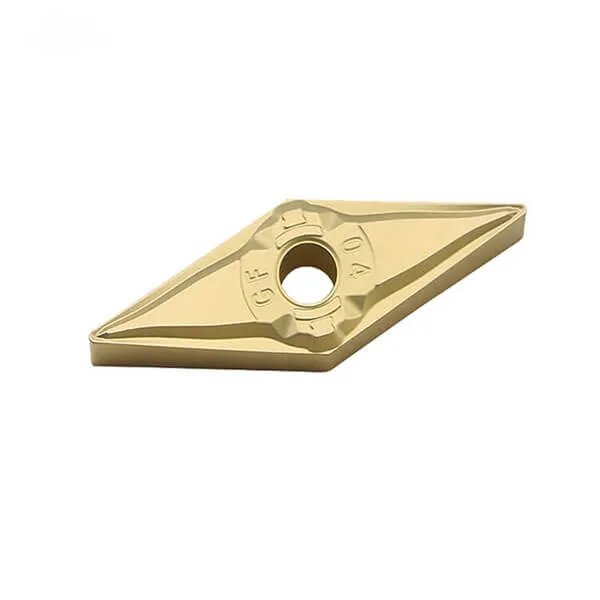
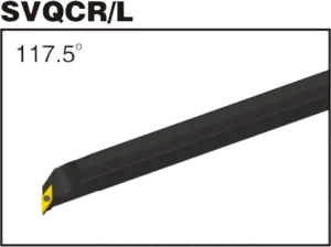
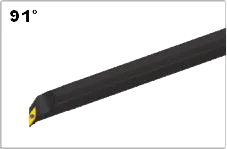
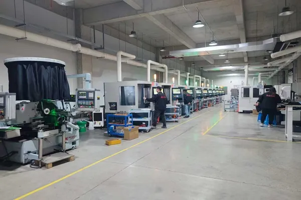
VBGTインサート VBGT 35°インサート角度:片面チップブレーカー付き5°ポジティブ・レーキ・インサート。スクリューオンインサート、長いチッピング材での切りくず処理用の高いポジティブすくい面を持つ仕上げ形状。ブレーカーの用途仕上げ加工適合ターニングツールホルダーSVQCR/L、SVUCR/L、SVQBR/L、SVUBR/LVBGTインサートタイプの範囲:VBGT1103/VBGT1604VBGTインサートは、異なるチップブレーカーとグレードを組み合わせることで、複数のオペレーションに対応することができます。材質:タングステンカーバイド; 今すぐお見積もりを 製品紹介 VBGTチップは、アルミ合金旋盤加工用に特別に設計されており、専用のチップブレーカを備えているため、アルミ合金の仕上げ加工で発生する切屑の絡み合いの問題を解消するだけでなく、優れた仕上げ面を実現します。 VBGTインサートの主な特徴 80° 菱形: 一般的な旋削加工に適した4つの切れ刃と強度を提供。ポジティブ・レーキ・アングル: これは、ネガティブレーキチップと比較して、わずかに滑らかな切削と低い切削力を提供することができます。チップブレーカーのオプション VBGTインサートは、特定の作業中にチップフローに影響を与えるための様々なチップブレーカー設計を備えています。コーティング: 耐摩耗性を向上させるため、TiN、TiCN、AlTiNなどでコーティングされることが多い。 VBGTインサート仕様 ここでは、コードの意味や重要な機能など、VBGTインサートの仕様について説明する:VBGT指定V: 80°のひし形。これにより、様々な旋削加工に安定性と強度を提供します。B: 5°の逃げ角(逃げ角)。G: チップブレーカーのタイプと穴のデザイン(メーカーによって異なる)。T: 内接円と厚みの精度の公差クラスを示す。一般的なVBGT寸法VBGTインサートは、他の多くのインサートと同様に、そのサイズを決定する番号を持っています:VBGT 110X0X:内接円(IC):0.125″ (1/8″)厚さ: 0.094″ (3/32″)Xはノーズ半径を表す(例:1=1/64″、0=シャープなコーナー)VBGT 160X0X:内接円(IC):0.625″ (5/8″)厚さ: 0.125″ (1/8″)Xはノーズ半径 VBGTインサートホルダー SVQBR/L SVUBR/L 超硬VBGTインサート寸法(ISOおよびANSI) ISO指定インサイテッド・サークル(IC)厚さコーナー半径 VBGT 11030211mm(約0.43インチ)3.18mm(1/8インチ)0.2mm(約0.008インチ) VBGT 11030411mm(約0.43インチ)3.18mm(1/8インチ)0.4mm(約0.016インチ) VBGT 16040416mm(約0.63インチ)4.76mm(3/16インチ)0.4mm(約0.016インチ) VBGT 16040816mm(約0.63インチ)4.76mm(3/16インチ)0.8mm(約0.031インチ) 例VBGT 110302 (ISO) 80°菱形, 正のレーキインサート.6.35mm(約1/4″)の内接円。厚さ3.18mm(約1/8″)。特定のチップブレーカー/穴の設計。 今すぐお見積もりを 超硬インサートの科学:その製造方法と強さの理由 超硬チップは、最も多用途で耐久性のある切削工具のひとつです。しかし、どのように作られるのでしょうか?また、なぜこれほど強いのでしょうか?このビデオでは、炭化タングステンの特性から製造工程まで、超硬チップの背後にある科学を探ります。 生産能力 お客様の用途に最適なVBGTインサートをお探しください! 今すぐお見積もりを