爬行銑削 vs 傳統銑削:綜合指南
在機械加工的世界裡,選擇正確的銑削策略可以決定您的專案成功與否。在這個領域中,有兩種基本方法佔據主導地位:爬坡銑削和傳統銑削。了解它們的差異、應用和最佳使用情境,對於在加工作業中取得優異的結果至關重要。
如果您不想閱讀複雜的文章,也可以查看 比較表 之間。
銑削方法簡介
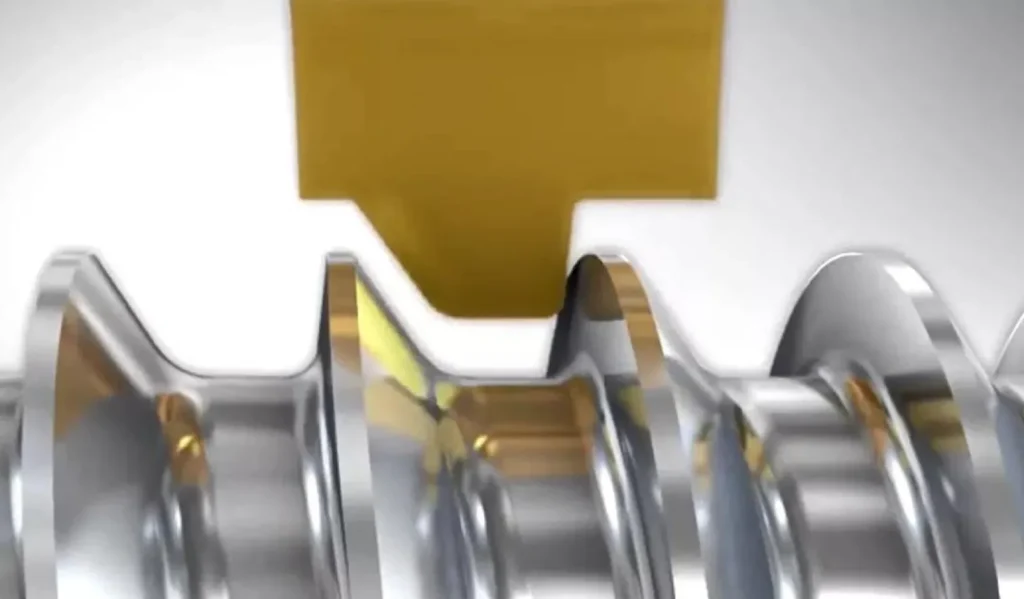
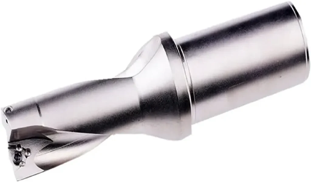
銑削是一種使用旋轉切削工具(例如 銑刀 銑削、可轉換銑削)。刀具旋轉方向與工件進給方向的關係定義了兩種截然不同的銑削方式。這些方法對表面加工品質、刀具壽命、切削力及整體加工效率有顯著的影響。
爬坡銑削與傳統銑削的差異主要在於相對於刀具旋轉的進給方向。這個看似簡單的變化,卻創造出截然不同的切削動態,各自具有獨特的優點和限制。
什麼是傳統銑削(向上銑削)?
傳統銑削也稱為上銑削,發生在工件逆著刀具旋轉方向進給時。在此方法中,切削刃開始時的切屑厚度為零,並在退出切削時逐漸增加到最大厚度。這會產生向上的切削動作,傾向於將工件抬離機床工作台。

傳統銑削的特性
傳統銑削的切削力會對工件產生向上和向外的拉力。這會導致工件振動和抖動,特別是在重切削時。在實際切削開始之前,切削刃與工件之間的初始接觸會產生摩擦動作,這會導致加工硬化並增加刀具磨損。
與爬坡銑削相比,傳統銑削的表面加工品質通常較為粗糙。切削動作會在加工表面留下輕微的撕裂外觀,這是由於切屑形成模式和向上的提升力造成的。
上切銑削的優勢
上切銑削有哪些優點?傳統銑削有幾個優點,特別是對於較舊的機床。由於切削力不會將工件拉入切刀,因此對於前導螺桿有後隙的機器而言,它的容錯性較高。這使得它對於可能難以精確控制的手動加工作業更加安全。
傳統銑削也是斷續切削的首選,以及加工切削時可能會抓取或拉扯的材料時的首選。切削刃的漸進式齧合提供了更受控制的材料切入。
上切銑削的缺點
上切銑削有哪些缺點?主要的缺點包括:表面加工品質較差、初期摩擦會導致刀具磨耗增加,以及維持切削所需的切削力較高。向上的切削力會造成工件翹起,導致尺寸不準確及潛在的安全危險。
傳統銑削所產生的震動和振動也會降低刀具壽命,並在精密應用中造成無法接受的表面粗糙度。
瞭解爬坡銑削(向下銑削)
爬銑或下銑發生於工件進給方向與刀具旋轉方向相同時。切削刃立即與最大切屑厚度接合,並在退出切削時減少至零。這會產生向下的切削動作,將工件牢牢推到機床工作台上。

爬行銑削的特性
爬坡銑削的切削力可將工件夾緊在工作台上,創造更穩定的切削條件。切削刃的立即完全嚙合消除了傳統銑削中的摩擦動作,使切削更乾淨,並延長刀具壽命。
由於平滑的切削動作以及切屑形成和排出切削區的方式,爬坡銑削的表面光潔度品質明顯較佳。
爬行銑削的優勢
為何在加工時選擇爬銑或俯銑呢?主要原因包括優異的表面光潔度、延長刀具壽命、降低切削力,以及更佳的尺寸精度。向下的夾持力可創造更穩定的切削條件,減少震動和振動。
爬坡銑削還能提供更好的排屑效果,因為切屑會被導離加工表面。這可防止切屑再次切削,並降低表面刮傷或損壞的可能性。
爬行銑削的缺點
爬坡銑削的主要限制是它需要剛性高且反向間隙最小的機床。在導螺桿磨損或間隙過大的機器上,爬銑可能會導致工件被拉入刀具,可能造成刀具破損或工件損壞。
比較摘要:爬坡式銑削和傳統式銑削哪一個更好?
爬坡銑削與傳統銑削哪一種較好,完全取決於您的特定應用需求和機器能力。
表面處理品質
爬坡銑削因其平滑的切削動作和適當的切屑形成,可持續產生優異的表面光潔度。傳統銑削通常會產生較粗糙的表面,需要額外的精加工處理。
工具壽命
爬坡銑削通常可消除初始的摩擦動作,提供更有效率的切削,從而延長刀具壽命。立即完全嚙合可減少刀具磨損和發熱。
切割力
雖然兩種方法都會產生切削力,但爬坡銑削的向下夾持力通常對工件的穩定性更有利。傳統銑削的向上力會造成工件移動和尺寸變化。
機器需求
傳統銑削對於有間隙的舊機器容錯性較高,而爬坡銑削需要剛性高、維護良好的設備才能達到最佳效果。
何時使用每種方法
何時使用爬坡切斷
何時使用爬坡銑削?爬坡銑削是精加工作業、精密加工以及使用現代 CNC 機器時的首選。它是實現嚴格公差和優異表面光潔度的理想選擇。
對於爬坡銑削與傳統銑削的鋁材而言,由於鋁材容易焊接到切削工具,爬坡銑削通常是首選。爬坡銑削的切削動作乾淨,可減少鋁金屬零件的翹邊形成,並產生更好的表面光潔度。
何時上銑比下銑更可取?
何時上銑比下銑更適合?當使用有明顯反衝力的舊式機器、加工斷續表面,或操作者的安全是手工操作的首要考量時,就會選擇傳統的銑削方式。
對於表面光潔度要求不高的粗加工,以及切削過程中容易抓傷或拉傷的材料時,它也是首選。
總結
了解爬坡銑削與傳統銑削的差異,對於最佳化您的加工作業是非常重要的。爬坡銑削通常在表面光潔度和刀具壽命方面提供優異的結果,但傳統銑削對於特定的應用和機器限制仍有其價值。
成功的關鍵在於將銑削方法與您的特定需求相匹配:機器能力、材料特性、表面光潔度要求以及操作限制。透過對何時及如何使用每種方法做出明智的決定,您可以在達到最佳結果的同時,最大限度地提高效率和刀具壽命。
爬坡銑削與傳統銑削的主要差異是什麼?
主要差異在於相對於刀具旋轉的進給方向。傳統銑削的進給方向與旋轉方向相反,而爬坡銑削的進給方向則與旋轉方向相同。
傳統銑削的最佳用途是什麼?
傳統銑削最適合有反衝力、切削中斷的舊式機器,以及需要刀具逐漸嚙合的情況。
哪種方法更適合鋁加工?
對於鋁材而言,爬坡銑削通常較為可取,因為其切削動作乾淨,並可減少形成疊邊。
為何選擇爬坡銑削而非傳統銑削?
在剛性較高的機器上,選擇彎曲銑削可獲得更佳的表面光潔度、更長的刀具壽命以及更佳的尺寸精度。
何時應該避免爬坡銑削?
避免在有明顯反間隙的機器上進行爬銑,或工件剛性不足以抵抗拉力時也要避免。
比較表
爬行銑削與傳統銑削比較
| 外觀 | 傳統銑削(向上銑削) | 爬坡銑削(向下銑削) |
|---|---|---|
| 製程特性 | ||
| 進料方向 | 針對切刀旋轉 | 搭配切刀旋轉 |
| 晶片厚度 | 零至最大值(逐步增加) | 最大值至零(逐步減少) |
| 切割力 | 向上和向外(提升工件) | 向下(夾持工件) |
| 工具參與 | 漸進式接觸初始摩擦 | 立即全面投入 |
| 優勢 | ||
| 表面處理 | 可接受粗加工 | 優異的加工品質 |
| 工具壽命 | 標準刀具壽命 | 延長刀具壽命 (20-50% 更長) |
| 機器需求 | 適用於有間隙的機器 | 需要堅固、精密的機器 |
| 安全性 | 手動操作更安全 | 需要仔細設定 |
| 振動控制 | 更多震動和抖動 | 切割更順暢、震動更小 |
| 缺點 | ||
| 表面品質 | 表面處理不良 | 優異的表面品質 |
| 工具磨損 | 摩擦導致磨耗增加 | 初始磨損最小 |
| 工件穩定性 | 提升力導致不穩定 | 優異的工件夾持 |
| 機器相容性 | 與舊式機器相容 | 不適用於有間隙的機器 |
| 風險因素 | 降低拉扯工件的風險 | 工件被拉入刀具的風險 |
| 最佳應用 | ||
| 操作類型 | 粗加工、中斷切割 | 精加工操作、精密加工 |
| 機器類型 | 舊式碾磨機、手動機 | 現代化 CNC 機器、剛性設定 |
| 材料適用性 | 硬質材料、鑄鐵 | 鋁、軟鋼、精密合金 |
| 公差要求 | 標準公差 (±0.005″ 或更寬) | 嚴格公差 (±0.001″ 至 ±0.002″) |
| 生產量 | 低至中等音量 | 中大批量生產 |
| 何時選擇 | ||
| 最佳選擇 |
- 機器有反衝力 - 需要手動加工 - 中斷的切割面 - 粗加工操作 - 安全是首要考量 |
- 表面處理是關鍵 - 嚴苛的公差要求 - 提供現代化 CNC 設備 - 鋁加工 - 高產量 |