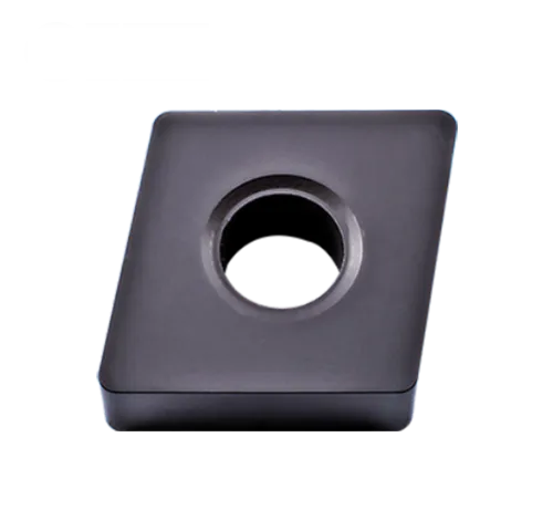
CNMAインサート
CNMA insert angle:0° Negative rake insert and no chipbreaker;
80°菱形旋回挿入;
Primary workpiece material: Hard material; cast Iron; steel;
Primary workpiece material code: P; H; K
Insert holding method: Pin; Clamp;
Breaker application: Roughing, semi-finishing, finishing;
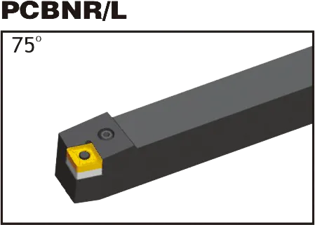
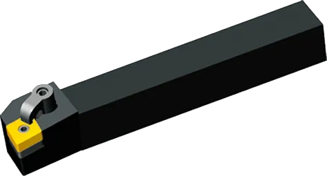
Matching cnma insert tool holder: PCBNR/L, PCLNR/L, MCLNR/L,MCBNR/L;
Grade: Both PVD and CVD;
Material : Tungsten Carbide;
CNMA insert tool holder


mclnr/l
CNMA insert Introduction:
CNMA Carbide Inserts: The Essentials
- 形: 80度の角度が含まれている菱形(ダイヤモンド)。
- クリアランス角度: 0 degrees
- 切断エッジ: 両面、費用対効果のためにインサートごとに2つの切断エッジを提供します。
- チップブレーカーの幾何学: Diverse range of chipbreaker styles from various manufacturers are available. These are tailored to specific materials and machining operations (roughing, finishing, etc.).
- 重要な用途: Primarily used for general turning operations and some facing work on a range of materials.
Common Materials CNMA Inserts are Used For
- 鋳鉄: 多くの鋳鉄用途に適しています。
Advantages of CNMA Inserts
- Cost-effective: Due to their double-sided design, offering longer tool life per insert.
- 汎用性: The range of grades and chipbreakers make them suitable for many machining applications.
- 強い幾何学的形状: The 80-degree diamond shape provides strength and rigidity for their size.
重要な考慮事項
- グレードを素材に一致させます: 適切な挿入コーティングと基質組成を選択することは、あなたが切る特定の材料の最適なツールの寿命と性能に不可欠です。
- 適切なチップブレーカーを選択します: チップブレーカーのジオメトリは、チップの形成と壊れた方法に大きく影響します。マシン操作の材料と種類に基づいて選択する必要があります。
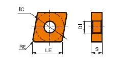
CNMA Insert Dimensions (ISO)
| TYPE | CNMA INSERT DIAMENTIONS(mm) | ||||
|---|---|---|---|---|---|
| LE | IC | S | DI | RE | |
| CNMA120404 | 12.9 | 12.7 | 4.76 | 5.16 | 0.4 |
| CNMA120408 | 12.9 | 12.7 | 4.76 | 5.16 | 0.8 |
| CNMA120412 | 12.9 | 12.7 | 4.76 | 5.16 | 1.2 |
| CNMA120416 | 12.9 | 12.7 | 4.76 | 5.16 | 1.6 |
| CNMA160608 | 16.1 | 15.875 | 6.35 | 6.35 | 0.8 |
| CNMA160612 | 16.1 | 15.875 | 6.35 | 6.35 | 1.2 |
| CNMA160616 | 16.1 | 15.875 | 6.35 | 6.35 | 1.6 |
| CNMA190612 | 19.3 | 19.05 | 6.35 | 7.94 | 1.2 |
| CNMA190616 | 19.3 | 19.05 | 6.35 | 7.94 | 1.6 |
Example: CNMA 120408
- 12: 12.7mm(約0.5インチ)の刻まれた円(IC)
- 04: 厚さ4.76mm(約0.187インチ)
- 08: 0.8mmのコーナー半径(約0.031インチ)
重要な寸法
刻まれた円(IC): インサート内に収まる最大の円の直径。一般的なICサイズは次のとおりです。
- 12.7mm(0.5″))
- 16mm(0.63″))
- 19.05mm(0.75″))
厚さ: 衝撃により、強度と使用可能な切断エッジの数が挿入されます。一般的な厚さには以下が含まれます。
- 3.18mm(0.125″))
- 4.76mm(0.187″))
- 6.35mm(0.25″))
コーナー半径: 最先端の表面仕上げと強度に影響します。一般的なサイズは次のとおりです。
- 0.4mm (0.016″))
- 0.8mm (0.031″))
- 1.2mm(0.047″))
The Science Behind Carbide Inserts: How They're Made and Why They're So Strong
超硬インサートは、入手可能な切削工具の中で最も多用途で耐久性のあるものの一部です。しかし、それらはどのように作られるのでしょうか?そして何が彼らをそんなに強いのでしょうか?このビデオでは、炭化タングステンの特性から製造プロセスまで、超硬インサートの背後にある科学を探求します。
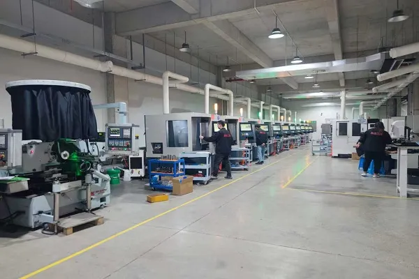
当社の生産能力