Inserto CCGT
CCGT insert angle:7° positive rake insert with a single-sided chip breaker;
Inserto rotazione rombico a 80 °;
Recommended for aluminum, fiberglass, plastic, teflon, brass;
Breaker application: Semi-finishing and finishing;
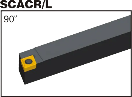
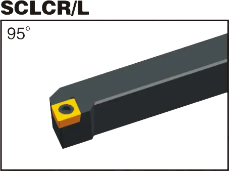
Matching CCGT insert tool holder: SCLCR/L and SCACR/L;
Material: Tungsten Carbide
Grade: Both PVD and CVD
CCGT insert tool holder
CCGT insert Introduction:
- C: Shape. The first “C” signifies a rhombic (diamond) shape with an 80-degree included angle.
- C: Clearance Angle. The second “C” indicates a 7-degree positive clearance angle.
- G: Tolerance. “G” denotes a medium tolerance range, though other precision tolerances may exist.
- T: Chipbreaker Style & Hole Configuration. This letter designates both the chip forming geometry and whether the insert has a central hole. Chipbreaker variations are numerous and manufacturer-specific.
- Cifre numeriche:
- Prime due cifre: Inscribed circle (IC) diameter in millimeters. Divide this by 25.4 to get the approximate inch equivalent.
- Due cifre successive: Thickness in millimeters. Divide by 25.4 for the inch conversion.
- Ultime due cifre: Nose radius in millimeters. Also divide by 25.4 for an inch approximation.
CCGT Carbide Inserts
Virtually all CCGT inserts are made from carbide-based materials. Here’s what you need to know:
- Substrato: The core carbide material determines the insert’s fundamental properties like toughness and wear resistance. Different compositions offer suitable balances for various applications.
- Rivestimento: Thin layers of advanced materials like TiN, TiAlN, CVD, or PVD are applied to the carbide substrate. These coatings enhance wear resistance, reduce friction, and improve performance in specific materials.
The Importance of Grade
Choosing the right carbide grade (substrate + coating) is crucial. This is matched to the workpiece material you’re cutting:
- Acciai
- Stainless Steels
- Cast Iron
- Non-ferrous metals (like aluminum)
- Hardened Materials
Let me know if you want to dive deeper into the following:
- Common chipbreaker styles and their applications
- How to choose the right CCGT insert grade for your material
CCGT Insert Dimensions (ISO)
| Designazione ISO | Cerchio inscritto (IC) | Spessore | Raggio dell'angolo |
|---|---|---|---|
| CCGT 060201 | 6.35mm (0.25") | 1.58mm (0.062") | 0.1mm (0.004") |
| CCGT 060202 | 6.35mm (0.25") | 1.58mm (0.062") | 0.2mm (0.008") |
| CCGT 060204 | 6.35mm (0.25") | 1.58mm (0.062") | 0.4mm (0.016") |
| CCGT 060208 | 6.35mm (0.25") | 1.58mm (0.062") | 0.8mm (0.031") |
| CCGT 09T308 | 9.52mm (0.375") | 3.18mm (0.125") | 0.8mm (0.031") |
Example: CCGT insert 060204
Rhombic shape with an 80-degree included angle
Angolo di clearance positivo a 7 gradi
Medium Tolerance
Configurazione di chipbreaker e fori specifici del produttore
6.35mm inscribed circle diameter (approx. 0.25″ in pollici)
2mm thick (approx. 0.079″ in pollici)
0.4mm nose radius (approx. 0.016″ in pollici)
The Science Behind Carbide Inserts: How They're Made and Why They're So Strong
Gli inserti in metallo duro sono alcuni degli utensili da taglio più versatili e durevoli disponibili. Ma come sono fatti? E cosa li rende così forti? In questo video esploreremo la scienza dietro gli inserti in metallo duro, dalle proprietà del carburo di tungsteno al processo di produzione.
La nostra capacità produttiva