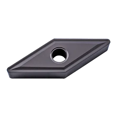
L'insert VNMG est fabriqué à partir d'un alliage métallique de haute qualité et d'une technologie avancée.
La surface est traitée avec un revêtement spécial pour prolonger la durée d'utilisation.
La conception unique en forme de V avec des angles négatifs de la plaquette VNMG garantit un usinage efficace et une grande stabilité.
La combinaison de différents brise-copeaux et de différentes qualités l'aidera à faire face à différentes conditions de travail et à de multiples opérations.
En outre, il présente les avantages d'une grande dureté, d'une grande efficacité, d'une grande précision, d'une résistance à la corrosion, d'une longue durée de vie, d'un aspect lisse et d'une grande qualité.
Caractéristiques principales
Forme : Les plaquettes VNMG sont triangulaires avec un angle inclus de 35°, offrant un bon équilibre entre résistance et tranchant. Cette forme offre trois arêtes de coupe utilisables.
Angle d'inclinaison négatif : La face de coupe est inclinée vers l'arrière à partir du tranchant, ce qui permet d'obtenir un tranchant solide et durable, bien adapté aux matériaux plus durs et aux coupes interrompues.
Angle de dégagement : Généralement 7° pour éviter le frottement contre la pièce à usiner.
Chipbreakers : Les plaquettes VNMG présentent souvent des géométries de brise-copeaux pour contrôler la formation et l'écoulement des copeaux pendant l'usinage, adaptées à des applications spécifiques.
Revêtements : Souvent revêtus de matériaux tels que TiN, AlTiN et autres pour améliorer la résistance à l'usure et la durée de vie de l'outil.
Spécification de l'insert VNMG
Comprendre le code VNMG
Les lettres et les chiffres de la désignation VNMG indiquent des détails importants :
V : Forme rhombique (diamant) de 35
N : Angle d'inclinaison négatif
M : Classe de tolérance (indique la précision de la taille)
G : Indique le type de trou et la conception du brise-copeaux (varie selon le fabricant).
Les chiffres :
En général, les deux premiers chiffres représentent le cercle inscrit (taille du triangle) en seizièmes de pouce (ou directement en millimètres pour les codes ISO).
Le troisième chiffre représente l'épaisseur en seizièmes de pouce.
Le dernier chiffre indique souvent le rayon du nez (plus il est petit, plus il est pointu).
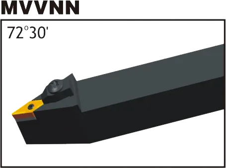
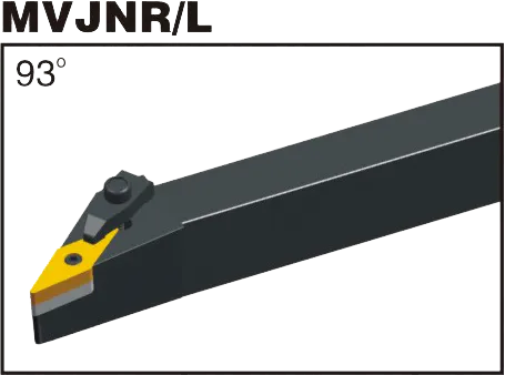
Porte-plaquette VNMG
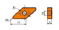
Dimensions des plaquettes en carbure VNMG (ISO ET ANSI)
vnmg insérer le formulaire complet
Désignation ISO
Désignation ANSI
Cercle inscrit (CI)
Épaisseur
Rayon de l'angle
VNMG 160404
VNMG331
16mm (0.63")
4,76 mm (0,187")
0,4 mm (0,016")
VNMG 160408
VNMG332
16mm (0.63")
4,76 mm (0,187")
0,8 mm (0,031")
VNMG 160412
VNMG333
16mm (0.64")
4,76 mm (0,188")
1,2MM(0,047'')
Exemple : VNMG 160408 (ISO)
Forme triangulaire à 35°, insert à inclinaison négative.
La science derrière les plaquettes en carbure : Comment elles sont fabriquées et pourquoi elles sont si résistantes
Les plaquettes en carbure comptent parmi les outils de coupe les plus polyvalents et les plus durables qui soient. Mais comment sont-elles fabriquées ? Et qu'est-ce qui les rend si résistantes ? Dans cette vidéo, nous allons explorer la science des plaquettes en carbure, des propriétés du carbure de tungstène au processus de fabrication.
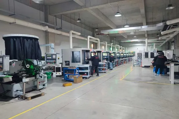
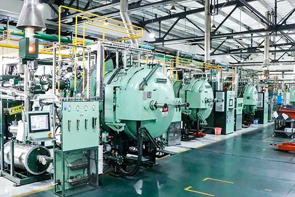
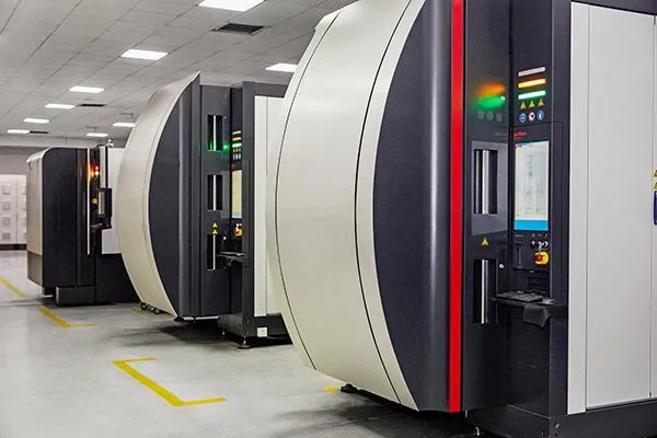
Notre capacité de production
Dans la fabrication moderne, les plaquettes en carbure de haute performance sont des outils indispensables, qui jettent les bases d'un traitement efficace et précis des métaux. Toutefois, ces plaquettes exceptionnelles ne naissent pas toutes seules ; elles sont soutenues par des machines de pointe.
Trouvez l'insert VNMG parfait pour votre application - Obtenez l'aide d'un expert !
Ce dont vous avez besoin, c'est d'un véritable vétéran de l'industrie des outils CNC. Laissez ONMY toolings vous aider à devenir le numéro 1 dans ce domaine.