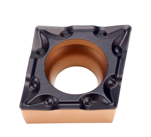

Insert CCMT
CCMT insert angle:7° Positive rake insert with a single-sided chipbreaker;
80° rhombic turning insert;
CCMT insert specifications: CCMT060204/CCMT09T304/CCMT09T308/CCMT090308/CCMT1204;
Recommended for steel, stainless steel, cast iron, heat resistant alloy;
Breaker Application: Semi-finishing, finishing, general purpose and rough turning;
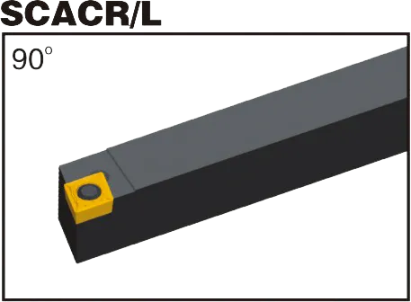
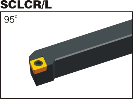
Matching CCMT insert turning tool holder: SCACR/L, SCLCR/L, SCFCR, SCLCR;
Material : Tungsten carbide
Grade: Both PVD and CVD;
CCMT insert tool holder
CCMT insert Introduction:
CCMT Inserts: The Essentials
- Forme: Rhombic (diamond) with an 80-degree included angle.
- Clearance Angle: 7 degrees (positive)
- Cutting Edges: Double-sided, offering two cutting edges per insert for cost-effectiveness.
- Chipbreaker Geometries: Diverse range of chipbreaker styles from various manufacturers are available. These are tailored to specific materials and machining operations (roughing, finishing, etc.)
- Key Uses: Ideal for turning, facing, and profiling operations on a range of materials.
Common Materials CCMT Inserts are Used For
- Steels: Various steel grades, including carbon and alloy steels.
- Stainless Steels: CCMT inserts can machine different stainless steel types.
- Cast Iron: Suitable for many cast iron applications.
- Some High-Temperature Alloys: Depending on the specific alloy and grade.
Advantages of CCMT Inserts
- Cost-Effective: Due to their double-sided design and wide availability.
- Versatile: The range of grades and chipbreakers make them suitable for many machining applications.
- Good Chip Control: Well-designed chipbreakers ensure effective chip flow and protect the workpiece, tool, and machine.
- Positive Rake Angle: This promotes efficient cutting and reduces cutting forces in many materials.
Important Considerations
- Match the Grade to Your Material: Choosing the right insert coating and substrate composition is crucial for optimal tool life and performance in the specific material you’re cutting.
- Select the Right Chipbreaker: The chipbreaker geometry significantly influences how chips are formed and broken. It should be chosen based on the material and type of machining operation.
- Machine Rigidity: Ensure your machine has enough rigidity and power to handle the cutting forces CCMT inserts can generate,
CCMT Insert Dimensions (ISO)
| TYPE | CCMT INSERT DIAMENTIONS(mm) | ||||
|---|---|---|---|---|---|
| LE | IC | S | DI | RE | |
| CCMT060204 | 6.4 | 6.35 | 2.38 | 2.8 | 0.4 |
| CCMT060208 | 6.4 | 6.35 | 2.38 | 2.8 | 0.8 |
| CCMT09T304 | 9.7 | 9.525 | 3.97 | 4.4 | 0.4 |
| CCMT09T308 | 9.7 | 9.525 | 3.97 | 4.4 | 0.8 |
| CCMT120404 | 12.9 | 12.7 | 4.76 | 5.56 | 0.4 |
| CCMT120408 | 12.9 | 12.7 | 4.76 | 5.56 | 0.8 |
| CCMT120412 | 12.9 | 12.7 | 4.76 | 5.56 | 1.2 |
Example: CCMT 09T308
- 09: Inscribed Circle (IC) of 9.52mm (approx. 0.375 inches)
- T3: Thickness of 3.18mm (approx. 0.125 inches)
- 08: Corner radius of 0.8mm (approx. 0.031 inches)
Key Dimensions
Inscribed Circle (IC): The diameter of the largest circle that fits within the insert. Common IC sizes include:
- 6,35 mm (0,25″)
- 9,52 mm (0,375″)
- 12,7 mm (0,5″)
Épaisseur: Impacts insert strength and the number of usable cutting edges. Common thicknesses include:
- 1.58mm (0.062″)
- 3,18 mm (0,125″)
- 4,76 mm (0,187″)
Corner Radius: Affects surface finish and strength at the cutting edge. Common sizes include:
- 0.2mm (0.008″)
- 00,4 mm (0,016″)
- 00,8 mm (0,031″)
The Science Behind Carbide Inserts: How They're Made and Why They're So Strong
Les plaquettes en carbure comptent parmi les outils de coupe les plus polyvalents et les plus durables disponibles. Mais comment sont-ils fabriqués ? Et qu’est-ce qui les rend si forts ? Dans cette vidéo, nous explorerons la science derrière les plaquettes en carbure, des propriétés du carbure de tungstène au processus de fabrication.
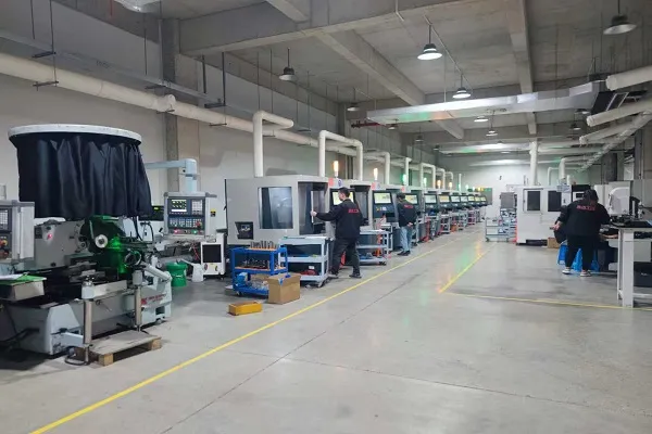
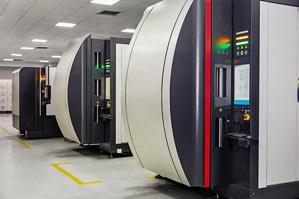
Notre capacité de production