Insert CCGT
CCGT insert angle:7° positive rake insert with a single-sided chip breaker;
80° rhombic turning insert;
Recommended for aluminum, fiberglass, plastic, teflon, brass;
Breaker application: Semi-finishing and finishing;
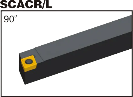
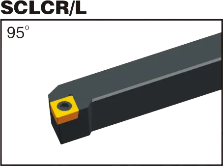
Matching CCGT insert tool holder: SCLCR/L and SCACR/L;
Material: Tungsten Carbide
Grade: Both PVD and CVD
CCGT insert tool holder
CCGT insert Introduction:
- C: Shape. The first “C” signifies a rhombic (diamond) shape with an 80-degree included angle.
- C: Clearance Angle. The second “C” indicates a 7-degree positive clearance angle.
- G: Tolerance. “g” denotes a medium tolerance range, though other precision tolerances may exist.
- T : Chipbreaker Style & Hole Configuration. This letter designates both the chip forming geometry and whether the insert has a central hole. Chipbreaker variations are numerous and manufacturer-specific.
- Chiffres numériques:
- Deux premiers chiffres: Inscribed circle (IC) diameter in millimeters. Divide this by 25.4 to get the approximate inch equivalent.
- Deux chiffres suivants: Thickness in millimeters. Divide by 25.4 for the inch conversion.
- Deux derniers chiffres: Nose radius in millimeters. Also divide by 25.4 for an inch approximation.
CCGT Carbide Inserts
Virtually all CCGT inserts are made from carbide-based materials. Here’s what you need to know:
- Substrate: The core carbide material determines the insert’s fundamental properties like toughness and wear resistance. Different compositions offer suitable balances for various applications.
- Enrobage: Thin layers of advanced materials like TiN, TiAlN, CVD, or PVD are applied to the carbide substrate. These coatings enhance wear resistance, reduce friction, and improve performance in specific materials.
The Importance of Grade
Choosing the right carbide grade (substrate + coating) is crucial. This is matched to the workpiece material you’re cutting:
- Aciers
- Stainless Steels
- Fonte
- Non-ferrous metals (like aluminum)
- Hardened Materials
Let me know if you want to dive deeper into the following:
- Common chipbreaker styles and their applications
- How to choose the right CCGT insert grade for your material
CCGT Insert Dimensions (ISO)
| Désignation ISO | Cercle inscrit (IC) | Épaisseur | Rayon de coin |
|---|---|---|---|
| CCGT 060201 | 6.35mm (0.25") | 1.58mm (0.062") | 0.1mm (0.004") |
| CCGT 060202 | 6.35mm (0.25") | 1.58mm (0.062") | 0.2mm (0.008") |
| CCGT 060204 | 6.35mm (0.25") | 1.58mm (0.062") | 0.4mm (0.016") |
| CCGT 060208 | 6.35mm (0.25") | 1.58mm (0.062") | 0.8mm (0.031") |
| CCGT 09T308 | 9.52mm (0.375") | 3.18mm (0.125") | 0.8mm (0.031") |
Example: CCGT insert 060204
Rhombic shape with an 80-degree included angle
Angle de dégagement positif à 7 degrés
Medium Tolerance
Configuration de chipbreaker et de trou spécifiques du fabricant
6.35mm inscribed circle diameter (approx. 0.25″ en pouces)
2mm thick (approx. 0.079″ en pouces)
0.4mm nose radius (approx. 0.016″ en pouces)
The Science Behind Carbide Inserts: How They're Made and Why They're So Strong
Les plaquettes en carbure comptent parmi les outils de coupe les plus polyvalents et les plus durables disponibles. Mais comment sont-ils fabriqués ? Et qu’est-ce qui les rend si forts ? Dans cette vidéo, nous explorerons la science derrière les plaquettes en carbure, des propriétés du carbure de tungstène au processus de fabrication.
Notre capacité de production