一站式CNC硬質合金刀片製造商

CNMM車刀
cnmm insert

CNMM車刀

CNMM insert angle:0° Negative rake insert with a single-sided chipbreaker;

80°菱形車削刀片;

Primary workpiece material: stainless steel, steel, brass, bronze, aluminium and cast iron;

Breaker application: Rough, heavy, semi-finshing;

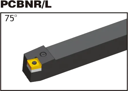
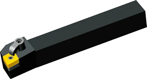
Matching TurningTool Holder: PCBNR/L, PCLNR/L, MCLNR/L,MCBNR/L;

Grade: CVD;

材質 : 碳化鎢

CNMM Insert Specifications

Heavy and semi-heavy machining require chip breakers designed for the task. Wide chip breakers optimize chip control at large depths of cut and high feeds. Cutting edge strength is maximized with a flat, negative land design. Conversely, finishing operations benefit from smaller chip breakers to facilitate chip breaking due to reduced cutting force. In finishing, prioritize cutting edge sharpness with a positive land and small edge honing. CNMM insert excel in roughing applications.

CNMM insert tool holder

CNMA 刀刃刀座 PCBNRL
CNMA 刀片刀柄 PCLNRL

MCLNR/L

CNMA 刀片刀柄 MCLNRL

CNMM insert Introduction

  • 1. Dimensions

    • 形狀: 夾角為 80 度的菱形(菱形)。
    • 間隙角: Negative (typically in the range of -5 to -7 degrees).
    • Tolerance: Medium (‘M’) is typical, but other tolerances may exist for specialized needs.
    • 內切圓 (IC): Determines the overall insert size (common: 12.7mm, 16mm).
    • 厚度: Impacts strength and cutting edge count (common: 4.76mm, 6.35mm).
    • 角落半徑: Affects strength and surface finish (common: 0.4mm, 0.8mm, 1.2mm).

    2. Chipbreaker Geometries

    • Hugely Important: Chipbreakers shape how chips form and break, ensuring efficient chip flow, tool protection, and workpiece finish.
    • Manufacturer-Specific: Chipbreaker designations are coded into the CNMM code (theMM). Refer to manufacturer catalogs for the specifics.
    • Match to Operation: Consider:
      • Workpiece material
      • Depth of cut (light vs. heavy)
      • Desired finish

    3. Hole Configuration

    • Central Hole: For secure clamping on toolholders.
    • Hole-less: Rely on alternative clamping mechanisms.
    • Toolholder Compatibility: Essential to match the insert’s hole configuration to your toolholder.

    4. Coating and Substrate

    • 塗層: Common types include TiN, TiAlN, CVD, and PVD. Each offers different wear resistance, thermal properties, and suitability for various materials.
    • Substrate: The base carbide material the coating is applied to. Compositions vary, offering toughness vs. wear resistance trade-offs.
    • Application-Specific: The right grade is crucial for optimal performance and tool life.

CNMM Insert Dimensions (ISO)

ISO 名稱內切圓 (IC)厚度轉角半徑
CNMM 12040412.7mm (0.5")4.76mm (0.187")0.4mm (0.016")
CNMM 12040812.7mm (0.5")4.76mm (0.187")0.8mm (0.031")
CNMM 12041212.7mm (0.5")4.76mm (0.187")1.2mm (0.047")
CNMM 16060816mm (0.63")6.35mm (0.25")0.8mm (0.031")

Example: CNMM 120408

  • Rhombic (diamond) shape with an 80-degree included angle
  • Negative clearance angle
  • Manufacturer-specific details within theMMdesignation
  • 12mm inscribed circle diameter (approx. 0.47″ 以英吋為單位)
  • 4mm thick (approx. 0.157″ 以英吋為單位)
  • 0.8mm 刀尖半徑(約 0.031″ 以英吋為單位)

The Science Behind Carbide Inserts: How They're Made and Why They're So Strong

硬質合金刀片是目前最通用、最耐用的切削工具之一。但它們是如何製作的呢?是什麼讓他們如此強大?在本影片中,我們將探索硬質合金刀片背後的科學,從碳化鎢的特性到製造流程。

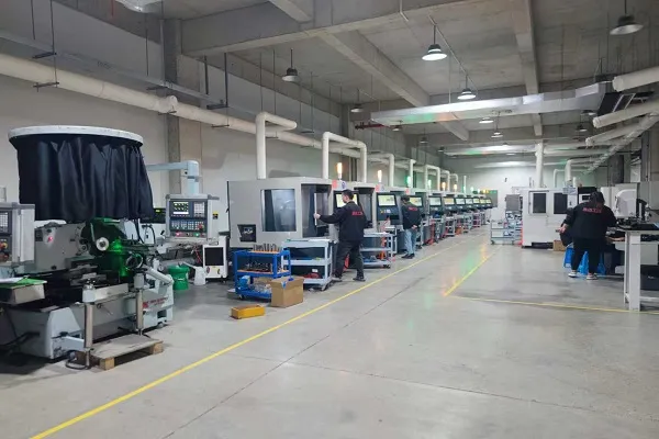
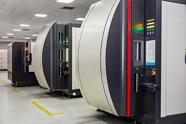
我們的生產能力

Find the Perfect CNMM Insert for Your Application – Get Expert Help!

捲動到頂部

今天您的銷售額猛增

您需要的是數控刀具行業的真正資深人士。讓ONMY工具幫助您成為該領域的No.1。

× 我怎麼幫你?