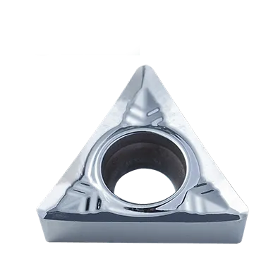

TCGTインサート
TCGT insert angle: 7° Positive Rake Insert with a single-sided Chipbreaker;
Screw-On Insert, finishing geometry with high positive rake face for chip control in long chipping materials;
Triangle carbide insert;
Breaker Application: Finshing machining;
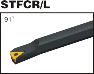
Matching Tool Holder: STFCR/L;STGCR/L,STTCR/L;
Range of TCGT insert types:TCGT090204/TCGT110204/TCGT16T304;
TCGT Insert can deal with multiple operations by combining different chip breakers and grades;
材料:タングステンカーバイド;
TCGT insert Meaning
Understanding the TCGT Insert Code
- T: Shape: Trigon (triangle)
- 子: Clearance Angle: 7 degrees (positive)
- G: 耐性:中容量は標準ですが、他の精密耐性が利用可能である可能性があります。
- T: ブレーカ形式 & 穴の構成。この文字は、特定のブレーカ形状と、インサートに穴があるかどうかを指定します。ブレーカのバリエーションは数多くあり、メーカーごとに異なります。
- 数字:
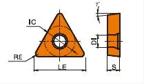
- 最初の 2 桁: 内接円 (IC) の直径 (ミリメートル単位)。おおよそのインチ相当値を取得するには、この数値を 25.4 で割ります。
- 次の 2 桁: 厚さ(ミリメートル)。インチに変換するには、25.4 で割ります。
- 下 2 桁: ミリメートルのコーナー半径。インチに変換するには、25.4で除算します。
TCGT insert tool holder

TCGT carbide Insert Dimensions (ISO)
| ISO指定 | 内接円 (IC) | 厚さ | コーナー半径 |
|---|---|---|---|
| TCGT 110202 | 11mm (0.433") | 2.38mm (0.094") | 0.2mm (0.008") |
| TCGT 110204 | 11mm (0.433") | 2.38mm (0.094") | 0.4mm (0.016") |
| TCGT 16T304 | 16mm (0.63") | 3.18mm (0.125") | 0.4mm (0.016") |
| TCGT 16T308 | 16mm (0.63") | 3.18mm (0.125") | 0.8mm (0.031") |
Example: TCGT 110204
- Trigon (triangle) shape
- 7-degree positive clearance angle
- 中程度の耐性
- メーカー固有のチップブレーカーとホール構成
- 内接円直径11mm(約0.43″ インチで)
- 2.38mm thick (approx. 0.094″ インチで)
- 0.4mm corner radius (approx. 0.016″ インチ単位)。
The Science Behind Carbide Inserts: How They're Made and Why They're So Strong
超硬インサートは、入手可能な切削工具の中で最も多用途で耐久性のあるものの一部です。しかし、それらはどのように作られるのでしょうか?そして何が彼らをそんなに強いのでしょうか?このビデオでは、炭化タングステンの特性から製造プロセスまで、超硬インサートの背後にある科学を探求します。
当社の生産能力


