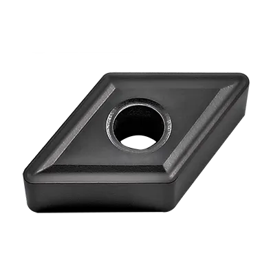
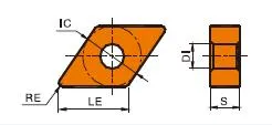
DNMGインサート
DNMG insert angle: 0° Negative Rake Insert with double-sided Chipbreaker;
55°ひし形旋削チップ。
Recommended for steel, stainless steel, and cast iron and etc;
Breaker Application: Rough, Semi-finishing, Finishing machining;
Matching DNMG insert holder: PDJNR/L, PDNN, MDJNR, MDPNN;
Application industry: DNMG Insert is widely applied in automobile, aerospace, 3C and other industries;
Range of DNMG insert types:DNMG150404/DNMG150408/DNMG331/DNMG332/DNMG431/DNMG432/DNMG/433;
グレード:PVDとCVDの両方。
材料:タングステンカーバイド;
DNMG insert specification
Our premium DNMG inserts are crafted from high-quality cemented carbide for exceptional performance.
Advanced quenching techniques and specialized surface coatings make them incredibly durable, resisting wear, heat, impact, and corrosion.
Plus, we’ll customize them to perfectly match your equipment and working conditions.
Expect unmatched accuracy, long service life, and outstanding cost-effectiveness.
That’s why these inserts are trusted worldwide in demanding industries like automotive, aerospace, and 3C manufacturing.
DNMG insert Meaning
Understanding the DNMG Insert Code
- D: 形状:ひし形(ひし形)、夾角55度。
- N: Clearance Angle: 0 degrees.
- M: Tolerance: Medium tolerance is standard, though other precision tolerances may exist.
- G: ブレーカ形式 & 穴の構成。この文字は、特定のブレーカ形状と、インサートに穴があるかどうかを指定します。ブレーカのバリエーションは数多くあり、メーカーごとに異なります。
- 数字:
- 最初の 2 桁: 内接円 (IC) の直径 (ミリメートル単位)。おおよそのインチ相当値を取得するには、この数値を 25.4 で割ります。
- 次の 2 桁: 厚さ(ミリメートル)。インチに変換するには、25.4 で割ります。
- 下 2 桁: ノーズ半径(ミリメートル単位)。インチに変換するには、25.4 で割ります。
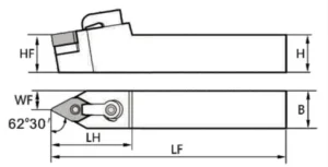
DNMG insert holder
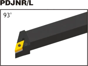

MDJNRL
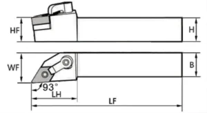
MDPNN
DNMG Insert Dimensions (ISO and INCH)
| DNMG Designation(ISO) | DNMG Designation(INCH) | 内接円 (IC) | 厚さ | Common Corner Radii |
|---|---|---|---|---|
| DNMG 110404 | DNMG331 | 11mm (0.433") | 4.76mm (0.187") | 0.4mm (0.016") |
| DNMG 110408 | DNMG332 | 11mm (0.433") | 4.76mm (0.187") | 0.8mm (0.031") |
| DNMG 150404 | DNMG431 | 15.875mm (0.625") | 4.76mm (0.187") | 0.4mm (0.016") |
| DNMG 150408 | DNMG432 | 15.875mm (0.625") | 4.76mm (0.187") | 0.8mm (0.031") |
| DNMG 150608 | DNMG442 | 15.875mm (0.625") | 6.35mm (0.25") | 0.8mm (0.031") |
| DNMG 190612 | DNMG543 | 19.05mm (0.75") | 6.35mm (0.25") | 1.2mm (0.047") |
Example: DNMG 150608
- Rhombic (diamond) shape with a 55-degree included angle
- 0 - クリアランスの角度
- 中程度の耐性
- メーカー固有のチップブレーカーとホール構成
- 15.875mm inscribed circle diameter (approx. 0.625″ インチで)
- 6.35mm thick (approx. 0.25″ インチで)
- 0ノーズ半径 0.8mm (約 0.031″ インチで)
The Science Behind Carbide Inserts: How They're Made and Why They're So Strong
超硬インサートは、入手可能な切削工具の中で最も多用途で耐久性のあるものの一部です。しかし、それらはどのように作られるのでしょうか?そして何が彼らをそんなに強いのでしょうか?このビデオでは、炭化タングステンの特性から製造プロセスまで、超硬インサートの背後にある科学を探求します。
当社の生産能力


