Comment choisir la bonne plaquette en carbure ?
I. Introduction
Dans la fabrication moderne, le choix de la bonne plaquette en carbure est essentiel pour améliorer l'efficacité de l'usinage, prolonger la durée de vie de l'outil et réduire les coûts. Un seul mauvais choix pour ce petit composant peut entraîner de mauvais états de surface, une usure prématurée de l'outil ou des perturbations dans la chaîne de production. Les plaquettes en carbure sont des outils de coupe remplaçables, principalement en carbure de tungstène avec des liants tels que le cobalt, largement utilisés dans l'usinage CNC, tournant, fraisageet forage. Ils résistent à des températures et des pressions élevées et conviennent à l'usinage de matériaux allant de l'acier aux composites. Cet article présente les facteurs clés et les étapes à suivre pour choisir la machine optimale. plaquette en carbure, Ce guide met l'accent sur la conception des plaquettes en carbure et sur le tableau de désignation des plaquettes en carbure, tout en explorant l'impact des plaquettes en carbure personnalisées et des plaquettes en carbure de forme sur l'usinage. Grâce à ce guide, vous apprendrez à sélectionner la meilleure plaquette pour vos besoins spécifiques, afin d'obtenir un usinage efficace.
II. Comprendre les bases des plaquettes en carbure
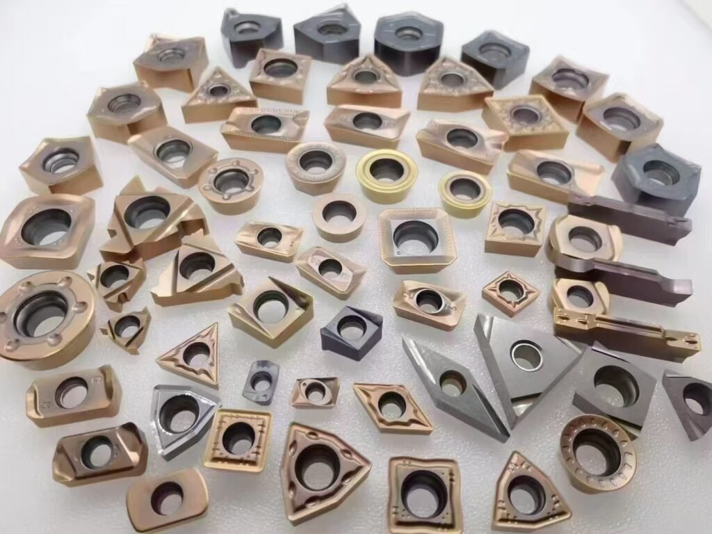
Les plaquettes en carbure sont des outils de coupe haute performance composés de particules de carbure de tungstène (WC) et de liants métalliques tels que le cobalt, formés par métallurgie des poudres. D'une dureté supérieure à HRA 90, ils offrent une résistance à la chaleur et à l'usure supérieure à celle des outils traditionnels en acier rapide, ce qui les rend idéaux pour la coupe à grande vitesse. Les types les plus courants sont les suivants angle de carrossage positif (pour les matériaux souples), le râteau négatif (pour les matériaux durs), et les variétés avec ou sans revêtement.
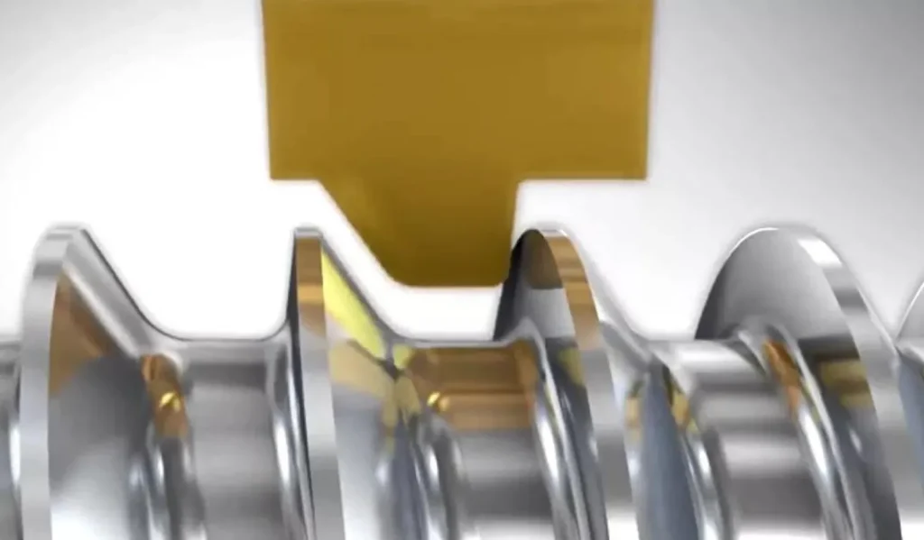
Elles sont largement utilisées dans les secteurs de l'automobile, de l'aérospatiale et de la fabrication. Par exemple, dans la production de pièces automobiles, ils tournent les vilebrequins ; dans l'aérospatiale, ils fraisent les composants en alliage de titane. L'importance de la sélection réside dans son potentiel à augmenter la productivité de 20%-50%, à améliorer la finition de surface et à réduire la fréquence de changement d'outil. Les plaquettes sur mesure et les plaquettes de forme optimisent davantage les scénarios d'usinage spécifiques. Un mauvais choix peut entraîner une accumulation de copeaux, une augmentation des vibrations ou une casse de l'outil, ce qui augmente les coûts.
III. Conception des plaquettes en carbure : Éléments clés à évaluer
La conception des plaquettes en carbure a un impact direct sur les performances de coupe, ce qui englobe la géométrie, les angles de coupe, la préparation des arêtes et les revêtements. Vous trouverez ci-dessous une analyse détaillée :
| Élément de conception | Description | Avantages | Inconvénients | Scénarios d'application |
|---|---|---|---|---|
| Géométrie et forme | La forme détermine les forces de coupe et la stabilité. Les formes les plus courantes sont les suivantes | |||
| - Rond (type R) | Haute résistance des arêtes, résistant aux chocs, idéal pour l'ébauche et le profilage. | Haute résistance, durable pour les coupes lourdes. | Efforts de coupe élevés, finition de surface inférieure. | Dégrossissage de la fonte ou de l'acier, par exemple, rainurage ou coupe lourde. |
| - Carré (type S) | Plusieurs arêtes de coupe (4-8), grande stabilité. | Rentable et durable pour l'usinage à plat. | Ne convient pas à l'usinage complexe ou fin. | Ebauche et surfaçage, par exemple, coupe plane de l'acier. |
| - Triangulaire (type T) | 3 arêtes, forces de coupe réduites, polyvalent. | Économique, très polyvalent. | Arêtes plus fragiles, sujettes à l'écaillage. | Tournage moyen, par exemple semi-finition de l'acier inoxydable ou de l'aluminium. |
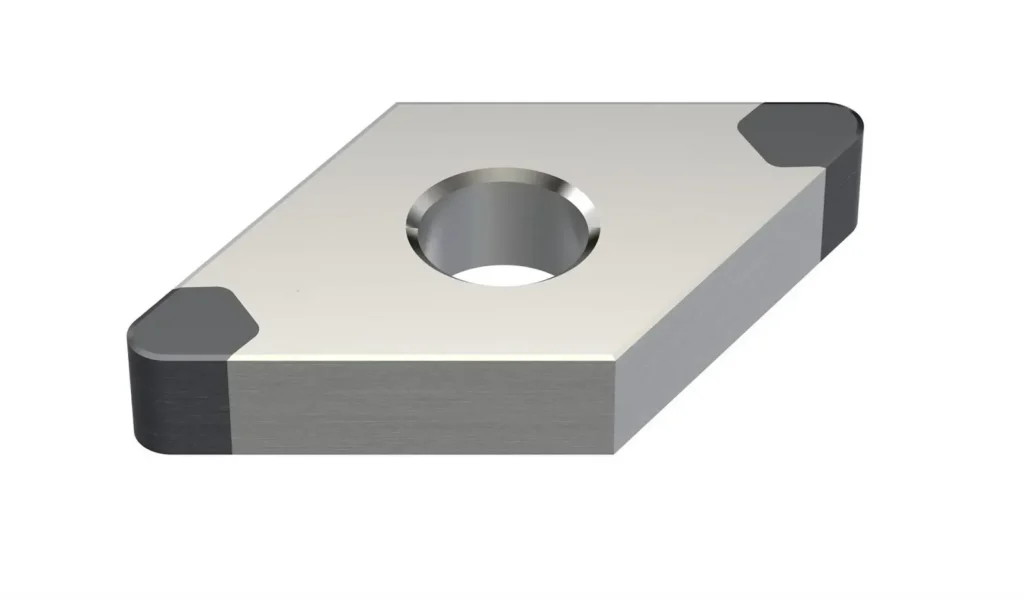
| - Rhombique 80° (type C) | Équilibre entre résistance et tranchant, bon contrôle des copeaux. | Polyvalent pour diverses opérations, coupe efficace. | Moins de bords (2-4). | Tournage général, par exemple, finition de l'acier ou de la fonte. |
| - Rhombique 55° (type D) | Rayon du nez réduit, idéal pour les coupes de précision. | Haute précision pour les formes complexes. | Moins de résistance, moins de résistance aux chocs. | Usinage de précision, par exemple trous de petit diamètre ou finition de l'aluminium. |
| Angles d'inclinaison et de dégagement | L'inclinaison positive réduit les forces de coupe (matériaux tendres) ; l'inclinaison négative améliore la stabilité (matériaux durs) ; l'inclinaison neutre est polyvalente. | Positif : Faible effort de coupe ; Négatif : Grande stabilité ; Neutre : Équilibré. | Positif : Négatif : forces plus élevées. | Choisissez en fonction du matériau, par exemple, positif pour l'aluminium, négatif pour l'acier. |
| Préparation des bords | Adouci (durabilité), chanfreiné (anti-écaillage), tranchant (faible frottement). | Adouci : Résistant à l'usure ; Chanfreiné : résistant aux chocs ; tranchant : haute finition. | Les bords tranchants s'usent rapidement ; l'adoucissement ne convient pas aux matériaux tendres. | Acier : adouci ; fonte : Chamfreiné ; aluminium : affûté. |
| Revêtements et qualités | Les revêtements prolongent la durée de vie de 2 à 5 fois. Les types les plus courants sont les suivants : | |||
| - Revêtement CVD | Dépôt à haute température, épaisseur de 3 à 20 µm, durable (par exemple, TiN, TiCN, Al2O3). | Haute résistance à la chaleur (>800°C), idéal pour l'ébauche. | Peut adoucir les bords, moins précis. | Usinage à grande vitesse de l'acier ou de la fonte. |
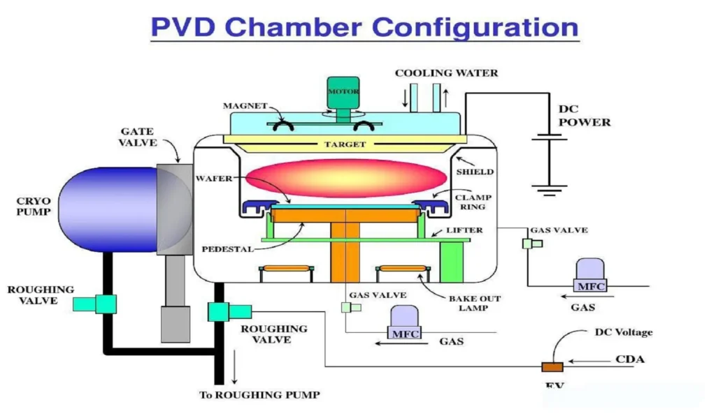
| - Revêtement PVD | Dépôt à basse température, épaisseur de 2 à 6 µm, arêtes vives (par exemple, TiAlN, CrN). | Idéal pour l'usinage à sec et de précision, résistant à la chaleur (>900°C). | Plus mince, moins résistant aux chocs. | Finition en acier inoxydable, aluminium, titane. |
| - Autres revêtements | Diamant (DLC, friction ultra-faible) ; multicouches (CVD/PVD combo). | Haute finition, antiadhésif. | Coût élevé, applications limitées. | Matériaux non ferreux comme l'aluminium, les matériaux composites. |
IV. Décodage du tableau de désignation des plaquettes en carbure
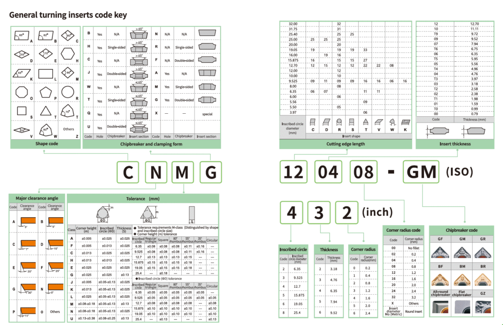
Le tableau de désignation des plaquettes en carbure, basé sur les normes ISO 1832 (pour les plaquettes de tournage) et ANSI, fournit des codes normalisés pour l'identification et la sélection. Les codes sont généralement composés de 7 à 10 caractères alphanumériques, par exemple :, CNMG 120408. Vous trouverez ci-dessous la convention de dénomination sous forme de tableau :
| Code Position | Signification | Exemple | Description |
|---|---|---|---|
| 1er : Forme | Indique la forme de l'insert | C (losange 80°), S (carré) | Formes courantes : R (rond), T (triangulaire), D (losange de 55°). |
| 2ème : Angle de dégagement | Indique l'angle de dégagement des bords | N (0°), P (11°) | 0° pour une inclinaison négative, 11° pour une inclinaison positive, affecte la force et la stabilité. |
| 3ème : Tolérance | Indique la précision des dimensions | M (moyenne), G (précision) | La tolérance a une incidence sur la précision de l'usinage ; G pour la finition. |
| 4ème : Serrage/Coupe-coupe | Indique le type de serrage et la conception du brise-copeaux | G (brise-copeaux double face), M (simple face) | Chipbreaker affecte le contrôle des puces ; G pour usage général. |
| 5ème-6ème : Taille | Indique le diamètre du cercle inscrit (IC) | 12 (12,7 mm), 16 (15,875 mm) | La taille détermine les dimensions de l'insert et doit correspondre au support. |
| 7e-8e : Épaisseur | Indique l'épaisseur de l'insert | 04 (4,76 mm), 06 (6,35 mm) | L'épaisseur influe sur la résistance, choisie en fonction de la profondeur de coupe. |
| 9e-10e : Rayon du nez | Indique le rayon de l'angle | 08 (0,8 mm), 04 (0,4 mm) | Petit rayon pour la finition, grand pour l'ébauche. |
| En option : Caractéristiques supplémentaires | Revêtement ou conception spéciale | Défini par le fabricant | Se référer aux catalogues des fabricants pour les spécificités, par exemple, les brise-copeaux sur mesure. |
Exemple: CNMG 432 (équivalent ANSI CNMG 432) - C pour losange 80°, N pour jeu 0°, M pour tolérance moyenne, G pour brise-copeaux, 4 pour taille 12,7 mm, 3 pour épaisseur 4,76 mm, 2 pour rayon de nez 0,8 mm. Les inserts personnalisés peuvent inclure des codes non standard, nécessitant la consultation du fabricant.
Identification des plaquettes de tournage
V. Facteurs à prendre en compte lors du choix des plaquettes en carbure
Le choix d'une plaquette implique de multiples facteurs, le matériau de la pièce à usiner étant le plus important. Vous trouverez ci-dessous un tableau de sélection des plaquettes pour différents matériaux :
| Matériau de la pièce | Caractéristiques recommandées de l'insert | Raison | Exemple d'application |
|---|---|---|---|
| Acier | Qualité P, revêtement CVD (TiCN, Al2O3), angle de coupe négatif, bord adouci, carré/80° rhombique. | Dureté moyenne, exige une résistance à l'usure et à la chaleur, une inclinaison négative pour la stabilité. | Tournage d'acier à teneur moyenne en carbone, par exemple, ébauche CNMG. |
| Fonte | Qualité K, revêtement CVD Al2O3, râteau positif/neutre, bord chanfreiné, rond/carré. | Fragile, nécessite un contrôle des copeaux, les plaquettes rondes résistent aux chocs. | Fraisage de face en fonte grise, plaquette ronde. |
| Acier inoxydable | Qualité M, revêtement PVD (TiAlN), angle de coupe positif, tranchant, 55°/80° rhombique. | Résistant et collant, le PVD réduit les frottements. | Finition de l'inox austénitique, 55° rhombique. |
| Alliage d'aluminium | Qualité N, non revêtu/revêtement DLC, angle de coupe positif, arête vive, triangulaire/55° rhombique. | Doux, collant, nécessite une faible friction et une finition élevée. | Finition de l'aluminium aérospatial, plaquette triangulaire. |
| Superalliages/Titane | Qualité S/H, revêtement TiAlN PVD, râteau négatif, bord adouci, carré/rond. | Haute résistance à la chaleur, résistance extrême à l'usure et aux chocs. | Ébauche d'alliages à base de nickel, insert carré. |
| Composites/non ferreux | Qualité dédiée, revêtement PVD/DLC, râteau positif, bord tranchant, triangulaire. | Nécessite une résistance à la corrosion et un faible frottement pour éviter d'endommager les fibres. | Usinage de la fibre de carbone ou du cuivre, insert triangulaire. |
Impact des opérations et conditions d'usinage:
- Dégrossissage: Grande profondeur de coupe (>2 mm), vitesse d'avance élevée (>0,3 mm/tr), faible vitesse. Nécessite des plaquettes robustes telles que des plaquettes à angle négatif, de forme ronde/carrée, à grand rayon de pointe (>0,8 mm) et revêtues de CVD pour résister aux chocs et à la chaleur élevés. Les plaquettes carbure personnalisées optimisent la conception des brise-copeaux, réduisant l'enchevêtrement des copeaux et augmentant l'efficacité de 10%-20%. Les plaquettes carbure profilées s'adaptent aux profils complexes des pièces (par exemple, l'usinage d'engrenages), minimisant les opérations ultérieures et améliorant la cohérence.
- Semi-finition: Profondeur moyenne (1-2 mm), avance moyenne (0,2-0,3 mm/tour), vitesse moyenne. Équilibre entre résistance et précision avec une inclinaison neutre, des formes triangulaires/80° rhombiques, un rayon de nez moyen (0,4-0,8 mm) et des revêtements multicouches. Les plaquettes personnalisées ajustent les angles des arêtes pour un meilleur état de surface ; les plaquettes de forme gèrent l'usinage de rainures spécifiques, réduisant ainsi les vibrations.
- Finition: Faible profondeur (<1mm), faible avance (<0,2mm/tour), vitesse élevée. Nécessite des plaquettes tranchantes telles que des plaquettes à inclinaison positive, des plaquettes rhombiques à 55°, des plaquettes à faible rayon de nez (<0,4 mm), des plaquettes PVD/non revêtues pour une finition et une précision optimales. Les plaquettes sur mesure offrent des rayons de nez ultra réduits, avec une précision de ±0,01 mm ; les plaquettes de forme conviennent aux surfaces complexes (par exemple, l'usinage de moules), garantissant une grande précision.
- Impact des plaquettes en carbure sur mesure: Les plaquettes en carbure sur mesure sont adaptées à des formes de pièces, des matériaux ou des conditions spécifiques. Par exemple, une plaquette personnalisée pour l'usinage de superalliages peut utiliser un revêtement multicouche spécialisé pour améliorer la résistance à la chaleur, ou un brise-copeaux unique pour les surfaces complexes afin de réduire l'accumulation de copeaux. Elles peuvent améliorer l'efficacité de 10%-30%, améliorer la qualité de la surface et réduire les changements d'outils, mais elles sont plus coûteuses, idéales pour les scénarios de haute précision ou de grand volume comme les pales de turbines aérospatiales.
- Impact des plaquettes en carbure de forme: Les plaquettes en carbure de forme sont conçues pour des profils de pièces spécifiques (par exemple, filets, engrenages, rainures), permettant l'usinage de formes complexes en une seule passe, réduisant ainsi les processus en plusieurs étapes. Par exemple, une plaquette de forme pour le formage des engrenages automobiles garantit des tolérances de ±0,02 mm, ce qui améliore l'efficacité et la cohérence de 20%-40%. Toutefois, leur conception complexe et les délais de production plus longs augmentent les coûts, ce qui les rend adaptés à la production répétitive et en grande quantité.
- Autres conditions:
- Vitesse de coupe: Les vitesses élevées nécessitent des revêtements résistants à la chaleur (par exemple, TiAlN) ; les vitesses faibles nécessitent des revêtements résistants à l'usure (par exemple, TiN). Plaquettes en carbure sur mesure utilisent des combinaisons de revêtements spécialisés pour les vitesses extrêmes ; les inserts de forme optimisent la forme des arêtes pour réduire les vibrations à grande vitesse.
- Vitesse d'avance et profondeur: Les valeurs élevées nécessitent une inclinaison négative et des arêtes adoucies ; les valeurs faibles nécessitent une inclinaison positive et des arêtes vives. Des inserts personnalisés optimisent la préparation des bords pour la stabilité ; inserts de formulaire assurer la cohérence des formes complexes.
- Méthode de refroidissement: L'usinage à sec utilise des revêtements PVD (faible frottement) ; l'usinage sous arrosage utilise des revêtements CVD (résistants à la corrosion). Les plaquettes sur mesure offrent des revêtements résistants à la corrosion pour l'usinage sous arrosage ; les plaquettes de forme réduisent la dépendance à l'égard du liquide de refroidissement.
- Compatibilité des machines: Faire correspondre le support (par exemple, la norme ISO) et l'alimentation pour éviter les vibrations.
- Coût et performance: Les revêtements haut de gamme, les inserts personnalisés ou de forme prolongent la durée de vie mais sont coûteux ; équilibrer l'investissement avec la productivité, idéal pour les scénarios de grand volume ou de précision.
VI. Guide étape par étape : Comment choisir la bonne plaquette en carbure
- Étape 1: Évaluer les besoins en matière d'usinage, y compris le matériau de la pièce (par exemple, l'acier a besoin d'une qualité P), le type d'opération (par exemple, l'ébauche a besoin de plaquettes rondes) et les exigences en matière de tolérance.
- Étape 2: Se référer au tableau de désignation des plaquettes en carbure pour la sélection initiale, par exemple, filtrer la série CNMG selon la forme et la taille.
- Étape 3: Évaluer les caractéristiques de conception des plaquettes en carbure, par exemple, choisir le revêtement TiAlN pour l'usinage des superalliages ou les plaquettes personnalisées/formées pour les pièces à usiner complexes.
- Étape 4: Consulter les données du fabricant (par exemple, les catalogues Sandvik ou Kennametal) et les échantillons d'essai pour valider les performances.
- Étape 5: Surveiller et ajuster en fonction des mesures de performance (par exemple, durée de vie de l'outil, rugosité de la surface), par exemple, changer de revêtement ou utiliser des plaquettes personnalisées/formées pour réduire l'usure.
VII. Erreurs courantes à éviter
- Ignorer la compatibilité matérielle: L'utilisation de la qualité P pour l'acier inoxydable entraîne une usure prématurée. Éviter: Correspondre aux normes ISO.
- Codes des désignations de surplomb: Une taille ou une forme incorrecte entraîne une incompatibilité. Éviter: Lire attentivement les codes et les tableaux.
- Négliger les revêtements ou les qualités: Manque de durée de vie, par exemple, ne pas utiliser de TiN pour l'acier. Éviter: Sélectionnez les revêtements CVD/PVD ou personnalisés.
- Ignorer le potentiel de l'insertion personnalisée/formulaire: Efficacité manquante pour les pièces complexes. Éviter: Consulter les fabricants pour des solutions sur mesure.
- Conseils de dépannage: Signes d'écaillage (arêtes trop vives) ou d'accumulation (revêtement mal adapté) ; corriger en ajustant l'inclinaison ou en utilisant des inserts sur mesure/de forme.
VIII. Conclusion
Le choix de la bonne plaquette en carbure est un processus systématique, avec la conception des plaquettes en carbure (par exemple, la forme, le revêtement), le tableau de désignation des plaquettes en carbure, les plaquettes en carbure personnalisées et les plaquettes en carbure de forme en tant qu'outils de base. En évaluant les matériaux, les opérations et les performances, vous pouvez améliorer considérablement l'efficacité de l'usinage, les plaquettes sur mesure et de forme offrant des avantages uniques pour les scénarios complexes ou à forte demande. Consultez des fournisseurs professionnels ou utilisez des outils en ligne pour obtenir des recommandations sur mesure, et explorez des sujets tels que "meilleures plaquettes en carbure pour l'aluminium" ou "fournisseurs de plaquettes en carbure" pour obtenir des informations plus approfondies.