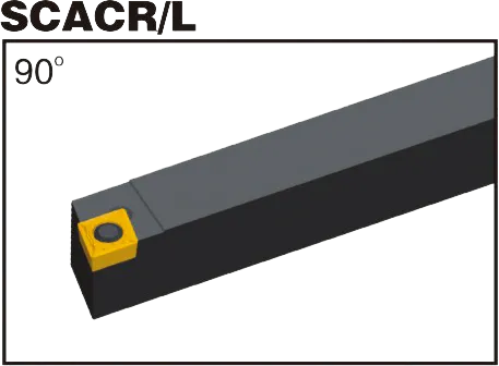
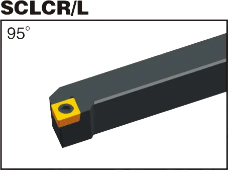
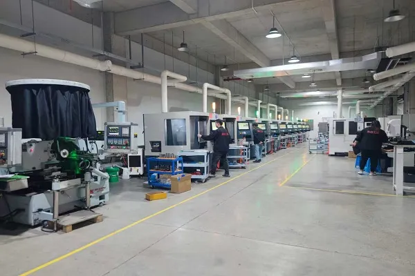
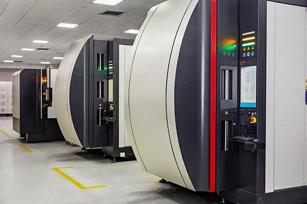
CCGTインサート CCGTチップ角度:片側チップブレーカー付き7°ポジティブすくいチップ;CCGTチップ角度:片側チップブレーカー付き7°ポジティブすくいチップ80°ひし形ターニングインサート;アルミニウム、グラスファイバー、プラスチック、テフロン、真鍮に推奨;ブレーカーの用途半仕上げと仕上げマッチング CCGTインサート 工具ホルダー:SCLCR/L および SCACR/L;;材質炭化タングステングレード:PVDとCVDの両方 今すぐお見積もりを CCGTインサートツールホルダー CCGTインサートの紹介: C: 形状。最初の "C "はひし形(菱形)を意味し、含まれる角度は80度。C: クリアランス角度。2つ目の "C "は、7度の正のクリアランス角を示す。G: 公差。"G "は中程度の公差範囲を示すが、他の精密公差が存在する場合もある。T: チップブレーカーのスタイルと穴の構成。この文字は、チップの成形形状と、チップに中央の穴があるかどうかを示します。チップブレーカーのバリエーションは多数あり、メーカーにより異なります。数字の桁数:最初の2桁 ミリメートル単位の内接円(IC)直径。これを25.4で割ると、おおよそのインチ換算になる。次ページ2桁: 厚さをミリメートルで表す。インチ換算は25.4で割ってください。下2桁 ノーズ半径(ミリメートル)。25.4で割るとインチ表示になります。CCGT超硬インサート事実上すべてのCCGTインサートは、超硬材料で作られています。ここで知っておくべきことがある:基質: 芯の超硬材料は、靭性や耐摩耗性などのチップの基本特性を決定します。異なる組成は、様々な用途に適したバランスを提供します。コーティング: TiN、TiAlN、CVD、PVDなどの先端材料の薄層を超硬基材にコーティングします。これらのコーティングは、耐摩耗性を高め、摩擦を減らし、特定の材料の性能を向上させます。グレードの重要性適切な超硬材種(基材+コーティング)を選択することが重要です。これは、切削する被削材に合わせます:鋼ステンレス鋼鋳鉄非鉄金属(アルミニウムなど)硬化材料もし、次のようなことをもっと深く知りたければ、私に知らせてほしい:一般的なチップブレーカーのスタイルとその用途材料に適したCCGTインサートグレードの選び方 CCGTインサート寸法(ISO) ISO指定インサイテッド・サークル(IC)厚さコーナー半径 CCGT 0602016.35mm(0.25インチ)1.58mm(0.062インチ)0.1mm(0.004インチ) CCGT 0602026.35mm(0.25インチ)1.58mm(0.062インチ)0.2mm(0.008インチ) CCGT 0602046.35mm(0.25インチ)1.58mm(0.062インチ)0.4mm(0.016インチ) CCGT 0602086.35mm(0.25インチ)1.58mm(0.062インチ)0.8mm(0.031インチ) CCGT 09T3089.52mm(0.375インチ)3.18mm(0.125インチ)0.8mm(0.031インチ) 例CCGTインサート 060204 ひし形で含まれる角度は80度7度のポジティブ・クリアランス・アングルミディアム・トレランスメーカー固有のチップブレーカーとホール構成内接円直径6.35mm(インチで約0.25)2mm厚(インチで約0.079)ノーズ半径0.4mm(インチで約0.016インチ) 今すぐお見積もりを 超硬インサートの科学:その製造方法と強さの理由 超硬チップは、最も多用途で耐久性のある切削工具のひとつです。しかし、どのように作られるのでしょうか?また、なぜこれほど強いのでしょうか?このビデオでは、炭化タングステンの特性から製造工程まで、超硬チップの背後にある科学を探ります。 生産能力 お客様のアプリケーションに最適なCCGTインサートをお探しください! 今すぐお見積もりを